Inst ToolsInst ToolsInst Tools
  • Courses
  • Automation
    • PLC
    • Control System
    • Safety System
    • Communication
    • Fire & Gas System
  • Instrumentation
    • Design
    • Pressure
    • Temperature
    • Flow
    • Level
    • Vibration
    • Analyzer
    • Control Valve
    • Switch
    • Calibration
    • Erection & Commissioning
  • Interview
    • Instrumentation
    • Electrical
    • Electronics
    • Practical
  • Q&A
    • Instrumentation
    • Control System
    • Electrical
    • Electronics
    • Analog Electronics
    • Digital Electronics
    • Power Electronics
    • Microprocessor
  • Request
Search
  • Books
  • Software
  • Projects
  • Process
  • Tools
  • Basics
  • Formula
  • Power Plant
  • Root Cause Analysis
  • Electrical Basics
  • Animation
  • Standards
  • 4-20 mA Course
  • Siemens PLC Course
Reading: Thermocouple Calibration
Share
Font ResizerAa
Inst ToolsInst Tools
Font ResizerAa
  • Courses
  • Design
  • PLC
  • Interview
  • Control System
Search
  • Courses
  • Automation
    • PLC
    • Control System
    • Safety System
    • Communication
    • Fire & Gas System
  • Instrumentation
    • Design
    • Pressure
    • Temperature
    • Flow
    • Level
    • Vibration
    • Analyzer
    • Control Valve
    • Switch
    • Calibration
    • Erection & Commissioning
  • Interview
    • Instrumentation
    • Electrical
    • Electronics
    • Practical
  • Q&A
    • Instrumentation
    • Control System
    • Electrical
    • Electronics
    • Analog Electronics
    • Digital Electronics
    • Power Electronics
    • Microprocessor
  • Request
Follow US
All rights reserved. Reproduction in whole or in part without written permission is prohibited.
Inst Tools > Blog > Calibration > Thermocouple Calibration

Thermocouple Calibration

Last updated: September 27, 2023 3:20 pm
Editorial Staff
Calibration Temperature Measurement
No Comments
Share
5 Min Read
SHARE

Thermocouples

Thermocouples measure temperature and are used quite often in process controls.

How They Work

When wires of two different thermoelectrically homogeneous materials are joined at one end and placed in a temperature gradient, a thermoelectric voltage (EMF) is observed at the other end. The connection is called the measuring junction.

On all thermocouples, the red lead is negative. The color of the other wire indicates the thermocouple type.

For example, on a J-type thermocouple, the positive wire is white. Tables for each type of thermocouple list the voltages produced at various temperatures.

Thermocouples should be checked whenever there are indications that the output is not accurate.

It may also be necessary to check a thermocouple that will be used for a measurement standard.

Input and Output Measurement Standards

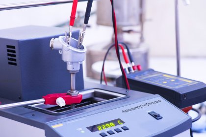
A temperature bath provides controlled temperatures for testing a sensor. A well in the temperature bath is used to hold the sensor during the accuracy check.

Another well is used to hold a measurement standard thermometer, it is used to confirm the actual bath temperature.

A second measurement standard thermometer is used to read the ambient temperature at the reference junction.

The sensor output signal and ranges determine the thermocouple output measurement standard.

Since the output is measured in millivolts, a millivolt meter is used to read the output.

Connections

Set up the temperature bath as a temperature input standard to the thermocouple.

Select the output standard with the appropriate range for reading millivolts.

Connect the red lead to the negative millivolt meter input and the white lead to the positive millivolt meter input.

Three Point Checks

Because no adjustments are possible, we can only check the calibration of a thermocouple sensor.

This check is generally done at three test point input values: ambient temperature, mid-range temperature, and upper value of the application range.

Recall that in a thermocouple, it is the difference in the temperature between the reference and the measuring junction that produces a millvoltage output.

Before inserting the thermocouple into the bath, determine the ambient temperature, which represents the temperature at the measuring junction of the thermocouple.

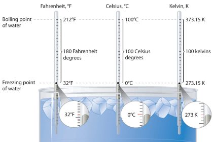
When using look-up tables that are referenced to 0 Deg., you must compensate for ambient temperature.

The millivolt value in the tables for the ambient temperature is added to the value from the sensor.

This compensated millivolt value is used to determine from the tables the correct temperature.

Also Read : Thermocouple Tables for millivolt to Temperature conversion

Thermocouple Transmitters

Calibration of temperature transmitters should be checked on a periodic basis.

Input and Output Measurement Standards

The temperature transmitter discussed here receives an input signal from a thermocouple.

A millivolt input signal will be needed for calibration, so a millivolt source can be used for the input standard.

A milliammeter can be used to measure the transmitter output. Use a standard thermometer to calculate the input signal compensation for the ambient temperature.

Finally, a power supply for the transmitter is necessary.

To calibrate a temperature transmitter with a millivolt meter as an input standard, you must compensate for any reference temperature other than 0 Deg. C ( 32 Deg. F.).

Connections

To make the input connections, the location of the reference junction must first be determined.

When thermocouple wires are used to connect the millivolt source to the transmitter, the reference junction is at the transmitter connection.

So, ambient temperature is measured in the transmitter housing. If copper wires are used, the reference junction is at the connection to the millvolt source, so measure ambient temperature at the millivolt source.

Always observe the polarity of the leads. Connect the negative output from the millivolt source to the positive transmitter terminal.

Connect the milliammeter in series with the transmitter and the power supply.

Setting the Equipment

Adjust the millivolt source and the milliammeter to the proper values as required, turn on equipment and begin calibration.
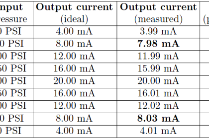
Five Point Check

Perform a five point check to determine if the transmitter is accurate according to specifications.

Accuracy of the Instrument

Adjust the zero shift first. It should be set with an input value of 10%.

With the zero properly set, a 10% input results in a 10% output. Adjust the span using a 90% input.

The zero and span may interact, check and readjust as required.

Also Read : Thermocouple Interview Questions

Don't Miss Our Updates
Be the first to get exclusive content straight to your email.
We promise not to spam you. You can unsubscribe at any time.
Invalid email address
You've successfully subscribed !

Continue Reading

Ammonia Gas Detector Working Principle and Calibration
Difference Between RTD, Thermocouple and Thermistor
Calculate Temperature Transmitter Output
Effect of Lead Wire Resistance on RTD
Closed tank DP Level Transmitter with wet leg Zero elevation Calibration
Magnehelic Gauge Calibration
Share This Article
Facebook Whatsapp Whatsapp LinkedIn Copy Link
Share
Leave a Comment

Leave a Reply Cancel reply

Your email address will not be published. Required fields are marked *

Stay Connected

128.3kFollowersLike
69.1kFollowersFollow
210kSubscribersSubscribe
38kFollowersFollow

Categories

Explore More

RTD Wheatstone Bridge Circuits
What is calibration?
Pressure Safety Valve Leak Test Procedure (PSV Testing)
Single Position Calibration of Temperature Bath
Calibration MCQ – Terminology and Glossary Questions
What is a Probe Thermometer? How to Calibrate and Use it?
Why 4 wire RTD Measurement Accuracy is better than 2 and 3 wire RTD?
Installation and Calibration of Pressure Transmitter

Keep Learning

Coriolis Mass Flow Meter Verification Procedure

Prover Tank Calibration and Mass Flow Meter Verification Procedure

Reliability Centered Maintenance (RCM)

What is Reliability Centered Maintenance? (RCM)

Radiation Pyrometer Working Principle

Radiation Pyrometer Working Principle

Spiral bimetallic thermometer principle

Spiral Bimetallic Thermometer Principle

How to Calibrate pH Electrode?

How to Calibrate pH Electrode?

RTD lead resistances Wiring

Resistance Temperature Detectors Working Principle

Smart Transmitter Calibration Tutorial Part 3

Smart Transmitter Calibration Tutorial Part 3

Technologies for Oxygen Gas Measurement

How to Calibrate Oxygen Analyzer? – O2 Sensor Testing Procedure

Learn More

Reliability Techniques for Analyzing Fault Tolerance in Industries

Reliability Techniques for Analyzing Fault Tolerance in Industries

Internal Parts of Globe Valve

How to Choose a Control Valve?

Flapper nozzle system

What is Flapper Nozzle System ?

Electron Spin Resonance Questions & Answers

Instrumentation of ESR Spectrometer

Programmable Logic Controller Practice Tests

Programmable Logic Controller Practice Tests

PLC Program using One Shot Rising Instructions

One Shot Rising and One Shot Falling Instructions in PLC

Fieldbus Pressure Transmitter Configuration

Foundation Fieldbus Pressure Transmitter Configuration

Permanent magnet moving coil instruments (PMMC)

Permanent Magnet Moving Coil Instruments (PMMC)

Menu

  • About
  • Privacy Policy
  • Copyright

Quick Links

  • Learn PLC
  • Helping Hand
  • Part Time Job

YouTube Subscribe

Follow US
All rights reserved. Reproduction in whole or in part without written permission is prohibited.
Welcome Back!

Sign in to your account

Username or Email Address
Password

Lost your password?