Bourdon Tube Pressure Gauge Working
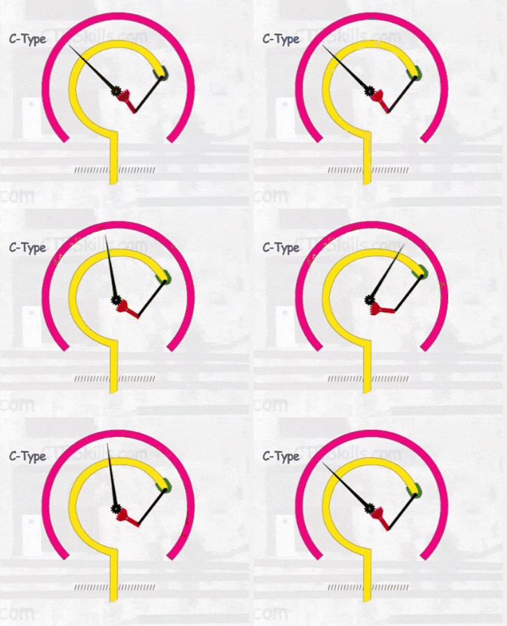
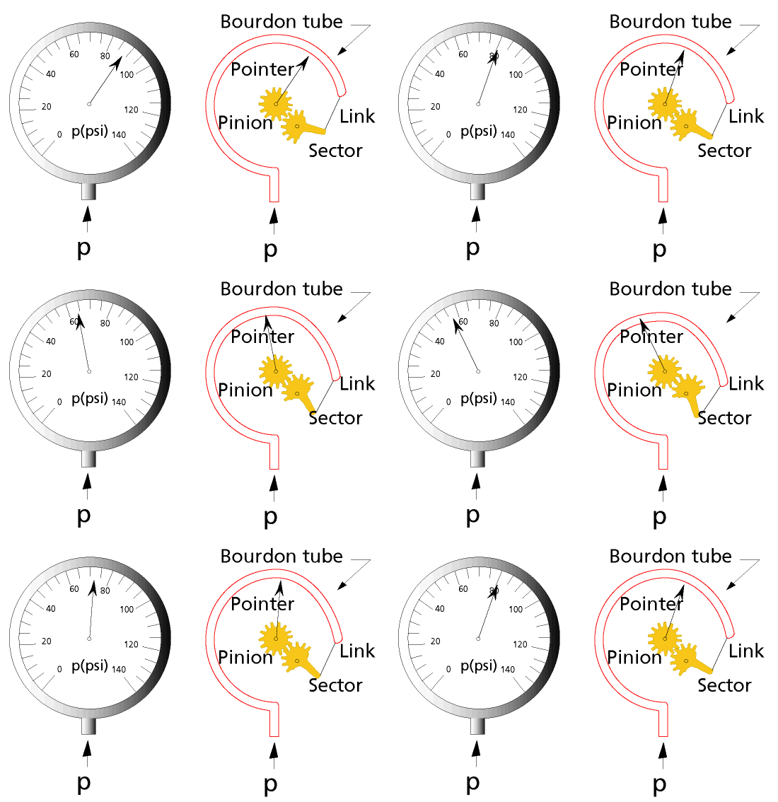
Bourdon tube pressure gauges are extensively used for local indication. This type of pressure gages were first developed by E. Bourdon in 1849. Bourdon tube pressure gauges can be used to measure over a wide range of pressure: form vacuum to pressure as high as few thousand psi. It is basically consisted of a C-shaped hollow tube, whose one end is fixed and connected to the pressure tapping, the other end free, as shown in fig. The cross section of the tube is elliptical.

When pressure is applied, the elliptical tube (Bourdon tube) tries to acquire a circular cross section; as a result, stress is developed and the tube tries to straighten up. Thus the free end of the tube moves up, depending on magnitude of pressure. A deflecting and indicating mechanism is attached to the free end that rotates the pointer and indicates the Pressure reading. The materials used are commonly Phosphor Bronze, Brass and Beryllium Copper. For a 2″ overall diameter of the C-tube the useful travel of the free end is approximately 1/8″ . Though the C-type tubes are most common, other shapes of tubes, such as helical, twisted or spiral tubes are also in use.
Also See: Proximity Sensor Working Animation
What a great site and very good animations, gives the solution even just looking at the animation .salute you
What a teaching style!!!!!
What are the difference between Bourdon tube manometer and bourdon tube pressure gauge. What I am searching for is the formal but the latter keep appearing
Great Animation
I would like to get quotation for Pressure Guage.
Hi, No sales here, only knowledge sharing. Thanks
Good work. thank you
How i wish i knew this site when i was a student!
Good work. Thank you
thank youuu
Animation is vivid , really good article.
what an animation, the animation tells us the way it works.