Inst ToolsInst ToolsInst Tools
  • Courses
  • Automation
    • PLC
    • Control System
    • Safety System
    • Communication
    • Fire & Gas System
  • Instrumentation
    • Design
    • Pressure
    • Temperature
    • Flow
    • Level
    • Vibration
    • Analyzer
    • Control Valve
    • Switch
    • Calibration
    • Erection & Commissioning
  • Interview
    • Instrumentation
    • Electrical
    • Electronics
    • Practical
  • Q&A
    • Instrumentation
    • Control System
    • Electrical
    • Electronics
    • Analog Electronics
    • Digital Electronics
    • Power Electronics
    • Microprocessor
Search
  • Books
  • Software
  • Projects
  • Process
  • Tools
  • Basics
  • Formula
  • Power Plant
  • Root Cause Analysis
  • Electrical Basics
  • Animation
  • Standards
  • 4-20 mA Course
  • Siemens PLC Course
Reading: Strain Gauge Animation
Share
Notification Show More
Font ResizerAa
Inst ToolsInst Tools
Font ResizerAa
  • Courses
  • Design
  • PLC
  • Interview
  • Control System
Search
  • Courses
  • Automation
    • PLC
    • Control System
    • Safety System
    • Communication
    • Fire & Gas System
  • Instrumentation
    • Design
    • Pressure
    • Temperature
    • Flow
    • Level
    • Vibration
    • Analyzer
    • Control Valve
    • Switch
    • Calibration
    • Erection & Commissioning
  • Interview
    • Instrumentation
    • Electrical
    • Electronics
    • Practical
  • Q&A
    • Instrumentation
    • Control System
    • Electrical
    • Electronics
    • Analog Electronics
    • Digital Electronics
    • Power Electronics
    • Microprocessor
Follow US
All rights reserved. Reproduction in whole or in part without written permission is prohibited.
Inst Tools > Blog > Animation > Strain Gauge Animation

Strain Gauge Animation

Last updated: March 23, 2020 7:08 pm
Editorial Staff
Animation
3 Comments
Share
1 Min Read
SHARE

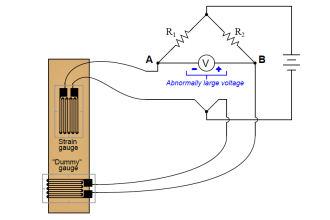
A strain gauge is a long length of conductor arranged in a zigzag pattern on a membrane.

When it is stretched, its resistance increases and Vice Versa.

Strain gauges are mounted in the same direction as the strain and often in fours to form a full ‘Wheatstone Bridge’.

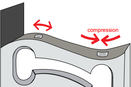
The animation represents what might happen if a strip of metal were fitted with four gauges.

An downward bend stretches the gauges on the top and compresses those on the bottom.

A load cell may contain several similar strain gauges elements.

Strain Gauge Animation

Strain Gauge Animation

Credits : rdpe.com

Don't Miss Our Updates
Be the first to get exclusive content straight to your email.
We promise not to spam you. You can unsubscribe at any time.
Invalid email address
You've successfully subscribed !

Continue Reading

Open Tank Level Measurement using DP Transmitters Animation
Spring and Diaphragm Pneumatic Actuators
Logic Gates Animation
Argonite/CO2 Flooding System Master & Slave Cylinder Operation
Pressure Transmitter Animation
Basics of Chromatograph Operation
Share This Article
Facebook Whatsapp Whatsapp LinkedIn Copy Link
Share
3 Comments
  • JoshWa2el says:
    June 8, 2020 at 10:54 am

    Thank you

    Reply
  • Tayeeba says:
    June 3, 2021 at 2:27 pm

    Hey, I really need this GIF for my report. Please kindly if you can send me I will be very very grateful to you, please.

    Email: [email protected]

    Reply
    • Hans Athmaram says:
      September 14, 2023 at 10:09 am

      Right click on the image and perform a “save image as”. Then you save as a gif.

      Reply

Leave a Reply Cancel reply

Your email address will not be published. Required fields are marked *

Stay Connected

128.3kFollowersLike
69.1kFollowersFollow
208kSubscribersSubscribe
38kFollowersFollow

Categories

Explore More

Relay Working Animation
Ultrasonic Flow Meters Working Principle
Scintillation Counter Principle
Basics of Butterfly Valves
Ultrasonic Sludge Blanket Level Meter Animation
Basics of Globe Valves
Radar Level Transmitter in Briddle level Measurement
Hall Effect Sensor Working Principle Animation

Keep Learning

Sinking and Sourcing Devices Operation

PLC Sinking and Sourcing Explanation

Area Velocity Flow Meter Principle

Area Velocity Flow Meter Principle

Rotameters Working

Rotameter Working Principle and Animation

Vibrating Fork Level Switch Working Animation

Vibrating Fork Level Switch Working Animation

load cell in deflection

Load Cell Working Principle

four-way-solenoid-valve-diagram

Four Way Solenoid Valve Working Principle

Impeller Flow Sensor

Impeller Flow Sensor Working Principle and Animation

Ultrasonic Flow meters Working Animation

Ultrasonic Flow Meters Animation

Learn More

Analyzers Questions and Answers

H2S Analyzers Questions & Answers

Single Line Diagram of UPS System

UPS Selection Factors for a Control System

Electronic Devices & Circuits Objective Questions

Electronic Devices & Circuits Quiz – Set 5

Motor Library in Studio 5000 PLC

Create User-Defined Data Types and Function Blocks in Studio 5000

Current to Pressure Converter Calibration Procedure

Current to Pressure (I/P) Converter Calibration Procedure

Difference Between LED and LCD

Difference Between LED and LCD

Difference Between MPCB and MCCB

Difference Between MPCB and MCCB

Electromagnetic Fields Objective Questions

Electromagnetic Subject Quiz

Follow US
All rights reserved. Reproduction in whole or in part without written permission is prohibited.
Welcome Back!

Sign in to your account

Username or Email Address
Password

Lost your password?