Inst ToolsInst ToolsInst Tools
  • Courses
  • Automation
    • PLC
    • Control System
    • Safety System
    • Communication
    • Fire & Gas System
  • Instrumentation
    • Design
    • Pressure
    • Temperature
    • Flow
    • Level
    • Vibration
    • Analyzer
    • Control Valve
    • Switch
    • Calibration
    • Erection & Commissioning
  • Interview
    • Instrumentation
    • Electrical
    • Electronics
    • Practical
  • Q&A
    • Instrumentation
    • Control System
    • Electrical
    • Electronics
    • Analog Electronics
    • Digital Electronics
    • Power Electronics
    • Microprocessor
  • Request
Search
  • Books
  • Software
  • Projects
  • Process
  • Tools
  • Basics
  • Formula
  • Power Plant
  • Root Cause Analysis
  • Electrical Basics
  • Animation
  • Standards
  • 4-20 mA Course
  • Siemens PLC Course
Reading: Magnetic Level Indicators Working Animation
Share
Font ResizerAa
Inst ToolsInst Tools
Font ResizerAa
  • Courses
  • Design
  • PLC
  • Interview
  • Control System
Search
  • Courses
  • Automation
    • PLC
    • Control System
    • Safety System
    • Communication
    • Fire & Gas System
  • Instrumentation
    • Design
    • Pressure
    • Temperature
    • Flow
    • Level
    • Vibration
    • Analyzer
    • Control Valve
    • Switch
    • Calibration
    • Erection & Commissioning
  • Interview
    • Instrumentation
    • Electrical
    • Electronics
    • Practical
  • Q&A
    • Instrumentation
    • Control System
    • Electrical
    • Electronics
    • Analog Electronics
    • Digital Electronics
    • Power Electronics
    • Microprocessor
  • Request
Follow US
All rights reserved. Reproduction in whole or in part without written permission is prohibited.
Inst Tools > Blog > Animation > Magnetic Level Indicators Working Animation

Magnetic Level Indicators Working Animation

Last updated: February 2, 2017 10:37 am
Editorial Staff
Animation How It Works Level Measurement
No Comments
Share
1 Min Read
SHARE

Magnatic Level Indicators Working Animation

Animation Credits : KANSAI Automation

Magnetic level indicators are low-maintenance alternatives to sight glasses and other level indicators. They provide non-invasive level indication while reducing leak points and fugitive emissions.

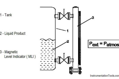
Magnetic level indicators consist of a chamber, a magnet equipped float which rises and lowers with the fluid level, reed switches and an indicator which is mounted to the chamber.

The indicator houses a column of small flags which indicate the level of the fluid in the chamber, based on the position of the float. As the fluid level rises and lowers, the float rises and lowers as well, and the flags are tripped from one orientation to the other.As the float rises and falls with the process level, tripping the flags (reed switches), it also stimulates any attached transmitters and switches, providing a signal back to the control system.

Also Read: Magnetic Float Switches Principle

Don't Miss Our Updates
Be the first to get exclusive content straight to your email.
We promise not to spam you. You can unsubscribe at any time.
Invalid email address
You've successfully subscribed !

Continue Reading

Effect of Temperature & Pressure on Level Measurement
Installation and Calibration of Level Transmitter
Comparison of Level Meters – Level Measurement Instruments
Displacer Level Sensor Working Animation
Level Transmitter and Level Gauge Design Tips
Sight Glass Level Measurement Principle
Share This Article
Facebook Whatsapp Whatsapp LinkedIn Copy Link
Share
Leave a Comment

Leave a Reply Cancel reply

Your email address will not be published. Required fields are marked *

Stay Connected

128.3kFollowersLike
69.1kFollowersFollow
210kSubscribersSubscribe
38kFollowersFollow

Categories

Explore More

How a 4-20mA Transmitter Works?
Magnetic Flow Meter Animation
Nuclear Interface Level Measurement Principle, Limitations, Installation and Calibration
Solenoid Valves Types, Principle & Animation
What is Contactor ?
Weight-based Level Measurement Principle
Variable Area Flow Meters – Principle, Advantages, Disadvantages
Bellows Pressure Sensors Working Principle Animation

Keep Learning

Probe Type Radar Level Transmitter

Contact Type Guided Wave Radar Level Transmitter Working Principle

Quartzoid Bulb Detector Working Principle

Fire Water Sprinklers Working Principle

Differential Pressure Measurement

Basics of Differential Pressure Level Transmitters

Stilling well in liquid level measurement

Stilling Well in Interface Level Measurement System

Float Level Measurement

Types of Level Measurement

Submersible Pressure Transmitter

What is a Submersible Pressure Transmitter? Principle, Advantages

Open Channel Flow Measurement Animation

Open Channel Flow Measurement Principle

How Buoyant Force instruments Works

How Buoyant Force instruments Works ?

Learn More

Gas Detectors Practical Problems and Troubleshooting

Gas Detectors Practical Problems and Troubleshooting

Thermocouple measurement and reference junction temperatures

Thermocouple Measurement and Reference Junction Temperatures

Transformers Interview Questions & Answers

Measurement and Instrumentation Objective Questions – Part 2

4-20mA Image

4-20mA Graphical Calculations

Control Systems Questions & Answers

Control Systems Objective Questions & Answers – Set 3

PLC attendance system design

Attendance System PLC Program using CX-Programmer

Fence grounding specifications

All About Electric Fence Gates

Ladder Logic for Stair-Case wiring using Toggle Switches

Ladder Logic for Stair-Case wiring using Toggle Switches

Menu

  • About
  • Privacy Policy
  • Copyright

Quick Links

  • Learn PLC
  • Helping Hand
  • Part Time Job

YouTube Subscribe

Follow US
All rights reserved. Reproduction in whole or in part without written permission is prohibited.
Welcome Back!

Sign in to your account

Username or Email Address
Password

Lost your password?