Inst ToolsInst ToolsInst Tools
  • Courses
  • Automation
    • PLC
    • Control System
    • Safety System
    • Communication
    • Fire & Gas System
  • Instrumentation
    • Design
    • Pressure
    • Temperature
    • Flow
    • Level
    • Vibration
    • Analyzer
    • Control Valve
    • Switch
    • Calibration
    • Erection & Commissioning
  • Interview
    • Instrumentation
    • Electrical
    • Electronics
    • Practical
  • Q&A
    • Instrumentation
    • Control System
    • Electrical
    • Electronics
    • Analog Electronics
    • Digital Electronics
    • Power Electronics
    • Microprocessor
  • Request
Search
  • Books
  • Software
  • Projects
  • Process
  • Tools
  • Basics
  • Formula
  • Power Plant
  • Root Cause Analysis
  • Electrical Basics
  • Animation
  • Standards
  • 4-20 mA Course
  • Siemens PLC Course
Reading: Sight Glass Level Measurement Principle
Share
Notification Show More
Font ResizerAa
Inst ToolsInst Tools
Font ResizerAa
  • Courses
  • Design
  • PLC
  • Interview
  • Control System
Search
  • Courses
  • Automation
    • PLC
    • Control System
    • Safety System
    • Communication
    • Fire & Gas System
  • Instrumentation
    • Design
    • Pressure
    • Temperature
    • Flow
    • Level
    • Vibration
    • Analyzer
    • Control Valve
    • Switch
    • Calibration
    • Erection & Commissioning
  • Interview
    • Instrumentation
    • Electrical
    • Electronics
    • Practical
  • Q&A
    • Instrumentation
    • Control System
    • Electrical
    • Electronics
    • Analog Electronics
    • Digital Electronics
    • Power Electronics
    • Microprocessor
  • Request
Follow US
All rights reserved. Reproduction in whole or in part without written permission is prohibited.
Inst Tools > Blog > Animation > Sight Glass Level Measurement Principle

Sight Glass Level Measurement Principle

Last updated: December 22, 2018 1:22 am
Editorial Staff
Animation Level Measurement
1 Comment
Share
5 Min Read
SHARE

Use of a sight glass is probably the simplest method of measuring liquid level.  The sight glass is attached to the outside of the tank so that the liquid level can be seen through the glass.  The sight glass is marked with graduations to allow the level to be measured.  The main disadvantage of this method is that it only gives level indication local to the vessel.

Sight Glass Level Measurement

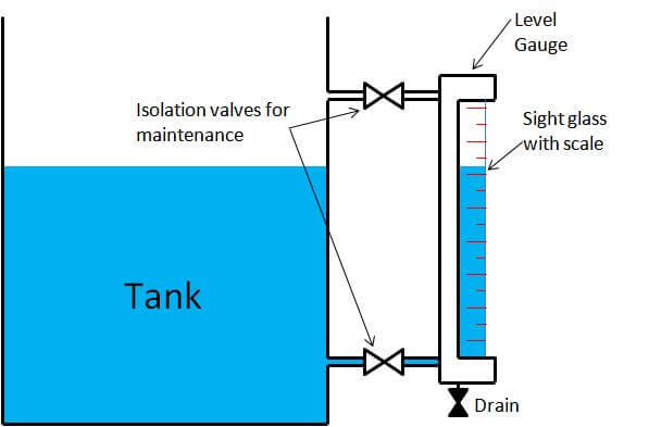
A visual indication of the level can be obtained when part of the vessel is constructed from transparent material or the liquid in a vessel is bypassed through a transparent tube. The advantage of using stop valves with the use of a bypass pipe, is the ease in removal for cleaning.

Types of Level Gauges:


Transparent Level GaugeLevel Gauge Working Animation

Transparent Level Gauges employ two transparent glasses fitted with a liquid chamber on either side. The liquid level is indicated as a result of difference in the transparent properties of the two media. For water / steam applications, an illuminator is mounted on the rear side of the gauge with its light rays deflected upward into the water column.

This enables the observer to see illuminated surface of the water as the light rays impinged on the surface of separation between water and steam are reflected back to the eye of the observer.

Magnetic Level Gauge

A float-containing magnet follows liquid level in the liquid chamber, which corresponds to the level in the tank. Position
of the float inside the chamber is indicated outside by bi-colored flapper embedded with magnet by 180 Deg rotation and setting into uniform color along the traverse of the float.

Reflex Level Gauge

The principle of Reflex Level Gauges is based on the difference in the refractive indices of liquid and vapor. The liquid column is contained within the recess of the liquid chamber behind the sight glass, which is clamped to the gauge body. The sight glass has prismatic right-angled grooves on the side facing the liquid and vapor space. Light rays entering from outside the gauge are either absorbed or reflected depending upon whether they enter the liquid or vapor space. When the ray of light encounters the surface of one of the grooves in the vapor space, it is reflected to the opposite surface of the grooves and from there, totally reflected back to the direction of observation.

Thus, vapor space appears as silvery white. When the light ray encounters the surface of the grooves in the liquid space, it is totally absorbed, thereby making the liquid behind the glass appear black. These gauges are used for measuring the level in a vessel.

Simple Sight glass level indicator

Advantages

  • Very simple
  • Inexpensive

Disadvantages

  • Not suitable for automated control.
  • Maintenance – requires cleaning
  • Fragile – easily damaged

Applications/Limitations

These are not highly suited for industrial applications as manual viewing and transmission of information is required by the operator.

Applications of such level measuring devices can be seen in tanks for the storage of lubricating oils or water. They provide a very simple means of accessing level information and can simplify the task of physically viewing or dipping a tank. They are, however, generally limited to operator inspection.

Sight glasses are also not suitable for dark or dirty liquids. This type should not be used when measuring hazardous liquids as the glass-tube is easily damaged or broken. In installations where the gauge is at a lower temperature than the process condensation can occur outside the gauge, impairing the accuracy of the reading.

Summary

Simple sight glasses are an older technology and are very seldom used for automatic control applications.

Don't Miss Our Updates
Be the first to get exclusive content straight to your email.
We promise not to spam you. You can unsubscribe at any time.
Invalid email address
You've successfully subscribed !

Continue Reading

What is ON/OFF Valve ?
Deluge Valve Working Principle
Motor Classic Control Circuits using Single Push button
Solenoid Valves Types, Principle & Animation
What are Mechanical Level Indicators? – Classification & Principle
Siemens Pressure Transmitter with Remote Seals Calculations
Share This Article
Facebook Whatsapp Whatsapp LinkedIn Copy Link
Share
1 Comment
  • kingsley says:
    August 18, 2016 at 9:40 am

    NICE ONE SIR , GOOD JOB KEEP IT UP!!!

    please how do we calibrate guided wave radar GWR level transmitter in the field.

    Reply

Leave a Reply Cancel reply

Your email address will not be published. Required fields are marked *

Stay Connected

128.3kFollowersLike
69.1kFollowersFollow
210kSubscribersSubscribe
38kFollowersFollow

Categories

Explore More

Servo Operated Float Level Measurement
Two Wire Sensor Working Principle and Animation
Ultrasonic Level Transmitter Working Principle
Types of Pneumatic Actuators Animation
Level Transmitter Calibration Procedure
Instruments Tapping Points – Common versus Individual
Understanding the Scan Cycle of SIEMENS PLC
Level Indicators Working Principle

Keep Learning

Interface level Measurement

Interface Level Measurement using DP Transmitter

Sinking and Sourcing Devices Operation

PLC Sinking and Sourcing Explanation

Capacitance Type Level Transmitter Working Principle

Capacitance Level Transmitter Animation

Chromatograph Principle

Basics of Chromatograph Operation

Junction Box Wiring

4-20mA Junction Box versus Fieldbus (FF) Junction Box

NO NC Contact Animation

Equivalent Logic Gates using PLC Ladder Diagrams

Venturi Flow Meter

Venturi Flow Meter – Working Principle, Advantages, Animation

bourdon-tube-pressure-gauge-working-animation

Working Principle of Pressure Gauge

Learn More

Advantages of Valve Regulated Lead Acid (VRLA) Batteries

Advantages of Valve Regulated Lead Acid (VRLA) Batteries

PLC Power Supply and Operating Voltages

PLC Power Supply and Operating Voltages

Ratio control

What is Ratio Control ?

TON Timer in RSlogix

Why is RTO used in the Place of TON Timer?

IoT Project Ideas for Beginners - Internet of Things

100 IoT Project Ideas for Beginners – Internet of Things

FBD Logic

Why different PLC Programming Languages were Developed?

Turbine-Compressor System Architecture

Turbine-Compressor System Architecture

Thermocouple Extension Lead Minimizer Circuit

Thermocouple Wires and Extension Lead Issues

Menu

  • About
  • Privacy Policy
  • Copyright

Quick Links

  • Learn PLC
  • Helping Hand
  • Part Time Job

YouTube Subscribe

Follow US
All rights reserved. Reproduction in whole or in part without written permission is prohibited.
Welcome Back!

Sign in to your account

Username or Email Address
Password

Lost your password?