Inst ToolsInst ToolsInst Tools
  • Courses
  • Automation
    • PLC
    • Control System
    • Safety System
    • Communication
    • Fire & Gas System
  • Instrumentation
    • Design
    • Pressure
    • Temperature
    • Flow
    • Level
    • Vibration
    • Analyzer
    • Control Valve
    • Switch
    • Calibration
    • Erection & Commissioning
  • Interview
    • Instrumentation
    • Electrical
    • Electronics
    • Practical
  • Q&A
    • Instrumentation
    • Control System
    • Electrical
    • Electronics
    • Analog Electronics
    • Digital Electronics
    • Power Electronics
    • Microprocessor
  • Request
Search
  • Books
  • Software
  • Projects
  • Process
  • Tools
  • Basics
  • Formula
  • Power Plant
  • Root Cause Analysis
  • Electrical Basics
  • Animation
  • Standards
  • 4-20 mA Course
  • Siemens PLC Course
Reading: Wedge Flow Meter Principle
Share
Font ResizerAa
Inst ToolsInst Tools
Font ResizerAa
  • Courses
  • Design
  • PLC
  • Interview
  • Control System
Search
  • Courses
  • Automation
    • PLC
    • Control System
    • Safety System
    • Communication
    • Fire & Gas System
  • Instrumentation
    • Design
    • Pressure
    • Temperature
    • Flow
    • Level
    • Vibration
    • Analyzer
    • Control Valve
    • Switch
    • Calibration
    • Erection & Commissioning
  • Interview
    • Instrumentation
    • Electrical
    • Electronics
    • Practical
  • Q&A
    • Instrumentation
    • Control System
    • Electrical
    • Electronics
    • Analog Electronics
    • Digital Electronics
    • Power Electronics
    • Microprocessor
  • Request
Follow US
All rights reserved. Reproduction in whole or in part without written permission is prohibited.
Inst Tools > Blog > Flow Measurement > Wedge Flow Meter Principle

Wedge Flow Meter Principle

The wedge Flow Meter measures the volumetric flow rate by calculating the differential pressure created across the wedge restriction in the pipeline.

Last updated: November 2, 2023 11:54 am
Editorial Staff
Flow Measurement
1 Comment
Share
3 Min Read
SHARE

A Wedge Flow Meter is preferably applied in difficult-to-meter line fluids, like air-entrained liquids, particular entrained liquids, high viscous liquids, or slurry liquids, which are abrasive or fibrous.

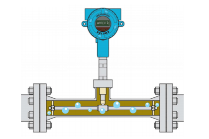
It is also applicable for clean liquids, gas/air, and steam. It consists of a measurement pipe with pressure taps in front and behind the flow element, a wedge restriction being welded into the measurement pipe from the top side.

Wedge Flow Meter

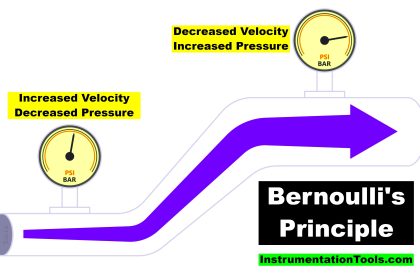
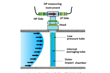
The pressure is measured in front of the wedge (high or dynamic pressure side) and behind the wedge (static or low-pressure side).

By determining the difference between these two measurements, which is called the differential pressure, the volume flow of the fluid can be calculated, as all other characteristics of the measuring points are constant.

Wedge Flow Meter

As the wedge has the profile of an isosceles triangle, the form is the same from both sides. So the measurement is possible in both directions.

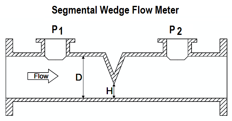
The line fluid is forced downward similar to a segmental orifice plate, but is guided along a slopping “wedge” shape rather than a sharp edge. The pressure taps are located upstream and downstream of the wedge and in all cases are equipped with sealed sensors.

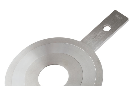
The differential pressure produced by the device is a function of the wedge segment opening (H) and the diameter of the body, “D” values as shown in the below figure.

The calculations for compressible flow are similar but must take account to temperature and adiabatic expansion and compressibility factors.

Solids and other debris easily pass under the restriction of the wedge meter. The inherent ruggedness of the restriction resists damage to its measuring edge.

If you liked this article, then please subscribe to our YouTube Channel for Instrumentation, Electrical, PLC, and SCADA video tutorials.

You can also follow us on Facebook and Twitter to receive daily updates.

If you liked this article, then please subscribe to our YouTube Channel for Instrumentation, Electrical, PLC, and SCADA video tutorials.

You can also follow us on Facebook and Twitter to receive daily updates.

Read Next:

  • DP Transmitter Interface Level
  • Types of Vortex Flow Sensors
  • Field Instrumentation Questions
  • 3-15 psi to 4-20mA Conversion
  • Why Turndown Ratio is important


Don't Miss Our Updates
Be the first to get exclusive content straight to your email.
We promise not to spam you. You can unsubscribe at any time.
Invalid email address
You've successfully subscribed !

Continue Reading

Flow Nozzle Principle, Advantages, Disadvantages, Applications
All About Vortex Flow Meters
Different Flow Measurement Technologies
How to Read Circular Chart Recorder for Flow Measurement?
Microwave Flow Sensor – Working Principle and Applications
How does an Orifice Measures Flow?
Share This Article
Facebook Whatsapp Whatsapp LinkedIn Copy Link
Share
1 Comment
  • James Spinney says:
    October 2, 2021 at 10:04 pm

    Hello
    I would like to add some information regarding the wedge flow meter. As most flow meters using differential pressure share a common flow equation, in principle, they are all created equal. Why you would select one geometry over another has to do with a couple of considerations.

    1. What is the Reynolds Number of the process at flowing conditions? The wedge meter has a very stable discharge coefficient down to an Re# of 500. This is one reason the wedge meter is well suited in viscous or low-velocity applications. The discharge coefficient is a factor for all flow primaries that corrects the common theoretical flow equation for the manufacturing tolerances, tap location, fluid profile, and turbulence associated to the installed geometry.

    2. The stability of the geometry under flowing conditions. The wedge meter is a very robust design that is well suited for withstanding impact and erosive forces. Therefore, the wedge meter is found often in slurry applications. However, it should be noted that a slurry flow application with a minimum Re# over 10000 could be measured by using a venturi as well with less permanent pressure loss.

    I would like to make a point regarding the orientation of the process taps. In almost all cases the preferred installation is to have the instrument taps at 90 degrees on the pipe rather than at the top of the pipe. With the tap and wedge aligned at the 90-degree position, solids can still easily pass along the bottom of the pipe.

    What we avoid is collecting entrained gas in the o-lets and impulse lines. Any amount of trapped gas will lead to error as the gas is compressible and will vary in amount as flow rates change and process conditions vary.

    Reply

Leave a Reply Cancel reply

Your email address will not be published. Required fields are marked *

Stay Connected

128.3kFollowersLike
69.1kFollowersFollow
210kSubscribersSubscribe
38kFollowersFollow

Categories

Explore More

Step by Step Guide for Gas Flow Meter Calibration
What is a Weigh Feeder?
Flow Transmitters Questions and Answers – Instruments Test
What is the Purpose of Orifice Plate Drain Hole and Vent Hole?
Troubleshooting DP type Transmitter Common Problems
Impulse Line – Purpose & Tapping Point Location
What are the Orifice Plate Flow Requirements?
Heat Tracing Problems

Keep Learning

Ultrasonic Flow meters Working Animation

Ultrasonic Flow Meters Animation

wedge Flow meter

What is a Segmental Wedge Flow Meter?

Oscillating Piston Flow Meters Animation

Oscillating Piston Flow Meters Working Principle

Flow Measurement Questions and Answers

80+ Flow Measurement Interview Questions and Answers

Annubar flow principle

Different Types of Flow Elements

Turbine Meter in Gas Metering System

Read Gas Composition from Gas Metering System using RS485 Protocol

Change-of-Quantity Flow Measurement

Change-of-Quantity Flow Measurement

flow-meter-accuracy-calculation

Impact of Flow Meter Accuracy

Learn More

Instrumentation Engineering Documents

Instrumentation Engineering Documents Questions Answers

DCS Program to Maintain Draft in Furnace

DCS Program to Maintain Draft in Furnace

Proof Testing of Safety Instrumented Systems

Proof Testing of Safety Instrumented Systems

What is IO-Link in Smart Manufacturing

What is IO-Link in Smart Manufacturing?

Industrial Instrumentation Questions & Answers

Industrial Instrumentation Questions & Answers

Basic components of a Thermowell

What is Thermowell and How-to choose Thermowell Probe Length ?

Variable Area Flow Meters

All About Variable Area Flow Meters

Analyzers Questions and Answers

Infrared Gas Analyzers Questions & Answers

Menu

  • About
  • Privacy Policy
  • Copyright

Quick Links

  • Learn PLC
  • Helping Hand
  • Part Time Job

YouTube Subscribe

Follow US
All rights reserved. Reproduction in whole or in part without written permission is prohibited.
Welcome Back!

Sign in to your account

Username or Email Address
Password

Lost your password?