An Orifice Meter is basically a type of flow meter used to measure the rate of flow of Liquid or Gas, especially Steam, using the Differential Pressure Measurement principle. It is mainly used for robust applications as it is known for its durability and is very economical.
As the name implies, it consists of an Orifice Plate which is the basic element of the instrument. When this Orifice Plate is placed in a line, a differential pressure is developed across the Orifice Plate. This pressure drop is linear and is in direct proportion to the flow rate of the liquid or gas.
Since there is a drop in pressure, just like the Turbine Flow meter, hence it is used where a drop in pressure or head loss is permissible.
Orifice Flow Meter
An orifice meter is a conduit and a restriction to create a pressure drop. A nozzle, venturi, or thin sharp-edged orifice can be used as the flow restriction.
In order to use any of these devices for measurement it is necessary to empirically calibrate them. That is, pass a known volume through the meter and note the reading in order to provide a standard for measuring other quantities.
Due to the ease of duplicating and the simple construction, the thin sharp-edged orifice has been adopted as a standard and extensive calibration work has been done so that it is widely accepted as a standard means of measuring fluids. Provided the standard mechanics of construction are followed no further calibration is required.
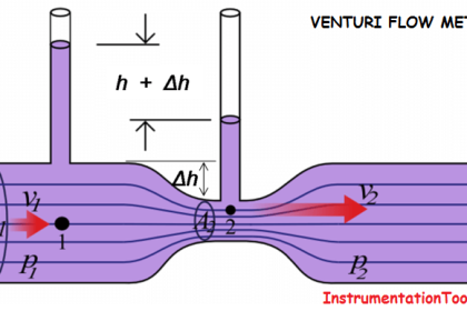
An orifice in a pipeline is shown in the below figure with a manometer for measuring the drop in pressure (differential) as the fluid passes through the orifice. The minimum cross-sectional area of the jet is known as the “vena contracta.”

How does an Orifice work?
As the fluid approaches the orifice the pressure increases slightly and then drops suddenly as the orifice is passed. It continues to drop until the “vena-contracta” is reached and then gradually increases until at approximately 5 to 8 diameters downstream a maximum pressure point is reached that will be lower than the pressure upstream of the orifice.
The decrease in pressure as the fluid passes through the orifice is a result of the increased velocity of the gas passing through the reduced area of the orifice.
When the velocity decreases as the fluid leaves the orifice the pressure increases and tends to return to its original level. All of the pressure loss is not recovered because of friction and turbulence losses in the stream.
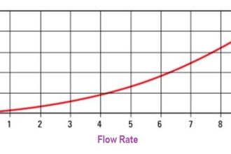
The pressure drop across the orifice ( ΔP in Fig.) increases when the rate of flow increases. When there is no flow there is no differential.
The differential pressure is proportional to the square of the velocity, therefore, follows that if all other factors remain constant, then the differential is proportional to the square of the rate of flow.
Orifice Construction

Inlet Section
A linearly extending section of the same diameter as the inlet pipe for an end connection for an incoming flow connection. Here we measure the inlet pressure of the fluid/steam/gas.
Orifice Plate
An Orifice Plate is inserted in between the Inlet and Outlet Sections to create a pressure drop and thus measure the flow.
Outlet Section
A linearly extending section similar to the Inlet section. Here also the diameter is the same as that of the outlet pipe for an end connection for an outgoing flow. Here we measure the Pressure of the media at this discharge.
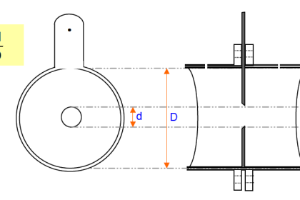
As shown in the adjacent diagram, a gasket is used to seal the space between the Orifice Plate and the Flange surface, to prevent leakage.
Sections 1 & 2 of the Orifice meter, are provided with an opening for attaching a differential pressure sensor (u-tube manometer, differential pressure indicator).
Material of Construction
The Orifice plates in the Orifice meter, in general, are made up of stainless steel of varying grades.
Shape and size of Orifice meter
Orifice meters are built in different forms depending upon the application-specific requirement, The shape, size, and location of holes on the Orifice Plate describe the Orifice Meter Specifications as per the following:
- Concentric Orifice Plate
- Eccentric Orifice Plate
- Segment Orifice Plate
- Quadrant Edge Orifice Plate
Concentric Orifice Plate
It is made up of SS and its thickness varies from 3.175 to 12.70 mm. The plate thickness at the orifice edge should not be exceeded by any of the following parameters:
- 1 – D/50 where, D = The pipe inside diameter
- 2 – d/8 where, d = orifice bore diameter
- 3 – (D-d)/8
*Beta Ratio(β): It is the ratio of the orifice bore diameter (d) to the pipe inside diameter (D).
Eccentric Orifice Plate
It is similar to a Concentric Orifice plate other than the offset hole which is bored tangential to a circle, concentric with the pipe, and of a diameter equal to 98% of that of the pipe. It is generally employed for measuring fluids containing
- Media having Solid particles
- Oils containing water
- Wet steam
Segment Orifice Plate
It has a hole which is a semi-circle or a segment of a circle. The diameter is customarily 98% of the diameter of the pipe.
Quadrant Edge Orifice Plate
This type of orifice plate is used for flow such as crude oil, high-viscosity syrups or slurries, etc.
It is conceivably used when the line Reynolds Numbers range from 100,000 or above or between 3,000 to 5,000 with an accuracy coefficient of roughly 0.5%.
Operation of Orifice meter
- The fluid flows inside the Inlet section of the Venturi meter having a pressure P1.
- As the fluid proceeds further into the Converging section, its pressure reduces gradually and it finally reaches a value of P2 at the end of the Converging section and enters the Cylindrical section.
- The differential pressure sensor connected between the Inlet and the Cylindrical Throat section of the Venturi meter displays the difference in pressure (P1-P2). This difference in pressure is in direct proportion to the flow rate of the liquid flowing through the Venturi meter.
- Further, the fluid passes through the Diverging recovery cone section and the velocity reduces thereby it regains its pressure. Designing a lesser angle of the Diverging recovery section helps more in regaining the kinetic energy of the liquid.
Advantages of Orifice meter
- The Orifice meter is very cheap as compared to other types of flow meters.
- Less space is required to Install and hence ideal for space constrained applications
- Operational response can be designed with perfection.
- Installation direction possibilities: Vertical / Horizontal / Inclined.
Limitations of Orifice meter
- Easily gets clogged due to impurities in gas or in unclear liquids
- The minimum pressure that can be achieved for reading the flow is sometimes difficult to achieve due to limitations in the vena-contracta length for an Orifice Plate.
- Unlike Venturi meter, downstream pressure cannot be recovered in Orifice Meters. Overall head loss is around 40% to 90% of the differential pressure .
- Flow straighteners are required at the inlet and the outlet to attain streamline flow thereby increasing the cost and space for installation.
- Orifice Plate can get easily corroded with time thereby entails an error.
- Discharge Co-efficient obtained is low.
Applications of Orifice meter
- Natural Gas
- Water Treatment Plants
- Oil Filtration Plants
- Petrochemicals and Refineries
If you liked this article, then please subscribe to our YouTube Channel for Instrumentation, Electrical, PLC, and SCADA video tutorials.
You can also follow us on Facebook and Twitter to receive daily updates.
Read Next:
- Venturi versus Orifice flow meters
- Flow Measurement Questions
- Types of Orifice Tapping
- Flow Meter Calibration Guide
- Orifice versus Restriction Orifice


Thanks Sir, Please how can we calibrate the concentric orifice plate for natural gas measurement and custody transfer validation.
Orifices are very rarely calibrated. The ISO, ASME, and AGA standards give the accuracy of the meter as long as it is manufactured and installed according to the details in the standard. Therefore it is much more common to inspect the orifice, or simply replace it, since the geometry is simple and replacement is low cost.
The secondary instrumentation, however, must be calibrated regularly. DP, Static Pressure, and Temperature instruments should be calibrated regularly.
All of these details should be included in the custody transfer contract.
The great thing that often gets forgotten with Orifice plates and other DP devices, is that they are manufactured to suit a specific flow. So while some people get hung up on “limited turn-down” they forget to tell the customer that the turn-down is real and not a function of a theoretical meter full scale.
Orifice plates also offer the user with the option to “suck it and see”. By installing an orifice plate with a best guess meter max and using initial flow data to re engineer a more suitable plate when the full range of flow is known. This helps to increase minimise pressure drop and increase accuracy of reading.
As for unrecoverable “pressure loss” I have seen a customer replace more than 50off orifice plates with vortex meters on a compressed air system, only to increase the pressure loss on reduced sized pipework (to get turndown from the vortex meters) to such a degree the compressor was not able to deliver enough air to the process.