In this article, we shall learn about Variable Area Flow meters. These are also called rotameters.
Variable Area Flow Meters
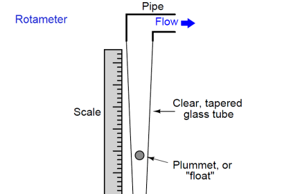
The variable area flow meter’s operation is based on the variable area principle: fluid flow raises a float in a tapered tube, increasing the area for the passage of the fluid. The greater the flow, the higher the float is raised.
The height of the float is directly proportional to the flowrate. With liquids, the float is raised by a combination of the buoyancy of the liquid and the velocity head of the fluid. With gases, buoyancy is negligible, and the float responds to the velocity head alone.
The float moves up or down in the tube in proportion to the fluid flow rate and the annular area between the float and the tube wall. The float reaches a stable position in the tube when the upward force exerted by the flowing fluid equals the downward gravitational force exerted by the weight of the float.
A change in flowrate upsets this balance of forces. The float then moves up or down, changing the annular area until it again reaches a position where the forces are in equilibrium. To satisfy the force equation, the variable area flow meter float assumes a distinct position for every constant flowrate.
However, it is important to note that because the float position is gravity dependent, variable area meters must be vertically oriented and mounted.
Applications
Variable-area meters are available as indicators, transmitters, recorders, local controllers, totalizers, and many combinations of these, with or without alarms. They are often used as purge meters for the sensing elements of other instrumentation and process equipment.
Other typical uses include measurement of the following fluids:
- Liquefied petroleum gas or other volatile liquids.
- Liquids that require heat to prevent congealing or freezing. (Jacketed meters are available that use steam or another heating medium.)
- Slurries or streams with suspended solids. (The meter manufacturer should be consulted regarding the application.)
- Acids
The following data is required for selecting a flow meter.
- minimum and maximum flow rate for the flow meter
- minimum and maximum process temperature
- size of the pipe
- accuracy
- back pressure inline or not?
- maximum process pressure
Advantages
The advantages of variable-area meters include
- a wide flow range (for example, 10:1),
- linear transmitter output, and
- minimal effect of gas compressibility.
Limitations
Limitations of variable area meters include
- their lack of availability in all materials;
- viscosity ceiling limits, which are provided by manufacturers and must be observed;
- their need to be installed vertically, which usually requires additional piping;
- the difficulty of checking calibration the difficulty of changing range; the requirement for a minimum back-pressure for gas applications;
- the fact that their magnetically coupled indicators or transmitters are subject to errors if metal particles accumulate; and
- the requirement for the shutdown of process lines to take these meters out of service, unless blocks and bypass are provided.
Installation
A variable-area meter should be installed in a location that is free from vibration and has sufficient clearance for occasional float removal for service or inspection. The meter should be readable and readily accessible for operation and maintenance. In general, when a meter is to be used in regulating service, it should be placed as close as possible to the throttling point.
These meters are always mounted vertically with an outlet on the top and inlet connection at the bottom.
Most variable area measurement is independent of upstream piping conditions. Elbows, valves, and other fittings have no effect on measurement accuracy.
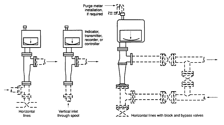
In a case where vertical and horizontal connections are possible, horizontal connections are preferred. Horizontal connections permit the use of plugged vertical openings as cleanout ports.
Block and bypass valves should be provided where operating conditions don’t allow shutdown as the meter is being replaced. The bypass line and valves should be the same size as the meter. Block valves are installed upstream and downstream of the meter. Care must be taken to ensure that valves are tightly closed while the meter is in service.
Piping connections of the variable area meter are shown in the following figure.
Interest to add any further points? Share with us through below comments section.
Author: Kalpit Patel
If you liked this article, then please subscribe to our YouTube Channel for Instrumentation, Electrical, PLC, and SCADA video tutorials.
You can also follow us on Facebook and Twitter to receive daily updates.
Read Next:
- Types of Flow Meters
- Selection of Level Gauges
- Fixed Area Flow Meters
- Differential Pressure Flow
- All About Turbine Meter