Inst ToolsInst ToolsInst Tools
  • Courses
  • Automation
    • PLC
    • Control System
    • Safety System
    • Communication
    • Fire & Gas System
  • Instrumentation
    • Design
    • Pressure
    • Temperature
    • Flow
    • Level
    • Vibration
    • Analyzer
    • Control Valve
    • Switch
    • Calibration
    • Erection & Commissioning
  • Interview
    • Instrumentation
    • Electrical
    • Electronics
    • Practical
  • Q&A
    • Instrumentation
    • Control System
    • Electrical
    • Electronics
    • Analog Electronics
    • Digital Electronics
    • Power Electronics
    • Microprocessor
Search
  • Books
  • Software
  • Projects
  • Process
  • Tools
  • Basics
  • Formula
  • Power Plant
  • Root Cause Analysis
  • Electrical Basics
  • Animation
  • Standards
  • 4-20 mA Course
  • Siemens PLC Course
Reading: What is IO-Link in Smart Manufacturing?
Share
Notification Show More
Font ResizerAa
Inst ToolsInst Tools
Font ResizerAa
  • Courses
  • Design
  • PLC
  • Interview
  • Control System
Search
  • Courses
  • Automation
    • PLC
    • Control System
    • Safety System
    • Communication
    • Fire & Gas System
  • Instrumentation
    • Design
    • Pressure
    • Temperature
    • Flow
    • Level
    • Vibration
    • Analyzer
    • Control Valve
    • Switch
    • Calibration
    • Erection & Commissioning
  • Interview
    • Instrumentation
    • Electrical
    • Electronics
    • Practical
  • Q&A
    • Instrumentation
    • Control System
    • Electrical
    • Electronics
    • Analog Electronics
    • Digital Electronics
    • Power Electronics
    • Microprocessor
Follow US
All rights reserved. Reproduction in whole or in part without written permission is prohibited.
Inst Tools > Blog > Common > What is IO-Link in Smart Manufacturing?

What is IO-Link in Smart Manufacturing?

In this post, we will learn the concept of IO-Link in smart manufacturing, types of data communicated in IO link and how it works.

Last updated: November 17, 2022 3:02 pm
Viral Nagda
Common
No Comments
Share
6 Min Read
SHARE

In this post, we will learn the concept of IO-Link in smart manufacturing.

Contents
Four Generations of AutomationWhat is IO-Link?Types of Data Communicated in IO-LinkHow does IO-Link Work?

Four Generations of Automation

Currently, in industrial automation, the fourth generation of technology is evolving and being used. There are four generations of automation.

What is IO-Link in Smart Manufacturing

The first revolution (1.0) dealt with shifting work from manual labor to systems working by steam-powered or water-powered engines and other machine tools.

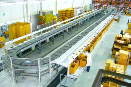
The second revolution (2.0) involved the use of steel and electricity in industries. Due to electrification, a huge amount of efficiency was increased and systems became more reliable. During this phase, production in assembly lines was started.

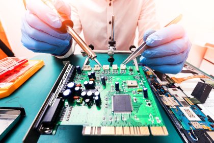
In the third revolution (3.0), the use of computers, PLCs, robotics, digital automation, and networks played a bigger role in increasing and controlling production to a great extent.

Now, the fourth revolution (4.0) has taken the third generation to a new level through the use of IoT (Internet of Things), cyber security, real-time data access, large and smarter network connectivity, open-source coding between all the manufacturers, cloud computing, and better collaboration.

In Industry 4.0, there are many technologies that help in smart coding and manufacturing. One thing in that is the IO link.

IO link is a standardized IO technology that helps in communicating with sensors and actuators with the PLC or other controllers in a fast, easy, and data-driven way. It is a point-to-point industrial networking protocol that provides a vast variety of data from sensors and actuators.

In this post, we will see the concept of the IO link in Industry 4.0 (smart manufacturing).

What is IO-Link?

IO link is an interface solution that communicates a wide variety of data with respect to the sensors and actuators.

For example, a normal sensor will either give you simple digital output or analog output.

But, the sensors or actuators with IO link protocol support provide other data apart from just signals. So, IO link is a point-to-point protocol that provides other information like the basic setup of the device, longevity prediction, effective operation/maintenance, diagnosis, and status information.

Just like the HART protocol, here too you can configure the device directly from PLC or a controller, and enable fast replacement settings. This easily increases the efficiency of automation, reduces downtime, and helps in decreasing maintenance activities.

One thing to note is that there are no extra cables for this data communication. The 3-wire cables used in sensors are used for IO link protocol; the same way as the HART protocol.

Types of Data Communicated in IO-Link

The following are the different types of data that are communicated in IO-link.

  • Service Data – SPDU (service protocol data unit), which is the same as SDO in Can-Open protocol; provides the user with all the basic information of sensor/actuator, initial start-up values, version of the device, serial number of the device, and initial configuration.
  • Process Data – It is the actual data information (like raw counts or current value) from the sensor/actuator; in the same way as PDO in the Can-Open protocol.
  • Event Data – Events that occur too rarely to be included in the process data, but should be reported without waiting for an SPDU to be queried can be delivered using IO-Link’s event facility. This allows standard or vendor-specific information about any alarms or informational messages to be delivered as they are encountered.

How does IO-Link Work?

IO-Link technology works on the master-slave protocol. Basically, an IO-Link Master device (usually of 8 ports) connects various slave devices (with IO-Link compatibility) to the PLC through a standard 3-wire connection and using M5, M8, or M12 ports.

The master can process digital as well as analog signals at a time and provides this data communication of sensors and actuators to the PLC.

The communication is fast (between 400 microseconds to 2 milliseconds). The data transfer is bidirectional and has serial point-to-point connectivity for signal and power.

One thing to remember is that a maximum of 20 m. the connection can be used for a device. The master can communicate with the PLC through Modbus, Profinet, Ethernet IP, and other standard protocols.

It helps simplify the maintenance process in a huge way; because, if suppose your sensor fails, and as the IO-Link protocol provides all the device information, the master device will transfer this sensor failure alarm to the PLC. The operator will come and rectify the issue accordingly.

It is to be noted that nowadays, a wide variety of sensors like ultrasonic sensors, pressure transducers, photoelectric sensors, proximity sensors, RFID, positioning systems, etc. use IO link protocol embedded in it. It has been designed keeping the fourth industrial revolution in mind.

In this way, we understand the concept of the IO link in smart manufacturing.

Don't Miss Our Updates
Be the first to get exclusive content straight to your email.
We promise not to spam you. You can unsubscribe at any time.
Invalid email address
You've successfully subscribed !

Continue Reading

Automation in Logistics Industry
Pneumatic Cylinder Movement Control with Timer Circuit
Career Scope in Electronics Engineering
Hysteresis
Comparison of Humidity Sensors – Industrial Instruments
How Many Types of Cable Glands Are There?
Share This Article
Facebook Whatsapp Whatsapp LinkedIn Copy Link
Share
Leave a Comment

Leave a Reply Cancel reply

Your email address will not be published. Required fields are marked *

Stay Connected

128.3kFollowersLike
69.1kFollowersFollow
208kSubscribersSubscribe
38kFollowersFollow

Categories

Explore More

Hydraulic and Pneumatic P&ID Diagrams and Schematics
What is an Absorption Chiller? – Working Principle
How to Use a Paint Thickness Gauge?
Best Engineering Mobile Apps on Google Play & App Store
Auto Cane Feed Control System using DCS – Sugar Factory
Difference between DSP and DAC – Digital Electronics
Difference Between Machine Learning and Artificial Intelligence?
How to Choose the Best Tungsten Grinders for Welders?

Keep Learning

Why Using VoIP Systems

Why Using VoIP Systems Can Save You and Your Business Money?

Electricity Generated From Wind Energy

How is Electricity Generated From Wind Energy?

What is Eddy Current and Eddy Current Loss

What is Eddy Current and Eddy Current Loss?

What is a Tactile Sensor? Principle, Advantages, and Applications

Learning Programming

How to Begin Learning Programming and Succeed?

Series Air Fuel Combustion Control

Combustion Control – Series and Parallel Air-Fuel Ratio Control

Why do Teenagers want to be Entrepreneurs

Why do Teenagers want to be Entrepreneurs?

CNC Programming - Definition, Types, and Tips

CNC Programming – Definition, Types, and Tips

Learn More

Control Systems Stability and Algebraic Criteria

Necessary Conditions for Stability & Non-Linear Systems

Top 300 Digital Signal Processing Projects (DSP)

Top 300 Digital Signal Processing Projects – DSP Project Ideas

different PLC brands of Distributed IO

What is Distributed IO? – Decentralized Peripherals in PLC

Control Valve in Nutshell - Valve Design and Selection Factors

Control Valve in Nutshell – Valve Design and Selection Factors

Ground Plate

Grounding of Telecommunication Systems

Capacitors Connected in Parallel

Series and Parallel Capacitors

How is Data Stored in Standard Modbus Protocol?

How is Data Stored in Standard Modbus Protocol?

tk3 calibration instrument

What is TK-3 Calibrator ?

Follow US
All rights reserved. Reproduction in whole or in part without written permission is prohibited.
Welcome Back!

Sign in to your account

Username or Email Address
Password

Lost your password?