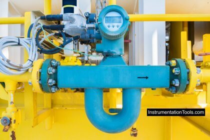
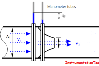
The vortex flow meter operates on the physical principle of the Karman vortex street.
When a fluid flows pass a bluff body, vortices are alternately forced on the side of that body and then detached or shed by the flow.
Vortex Flow Sensor
The frequency of vortex shedding is proportional to the mean flow velocity and therefore the volumetric flow (with Reynolds > 4000) St = Fd/V
Vortex frequency = St.v/d
St = strouhal number (dimensionless)
v = velocity fluid (m/s)
d = width of bluff body (m)
Alternating pressure changes caused by the vortex are transmitted via a lateral port (sensor) into the bluff body.
The sensor detects the pressure pulses and converts these into electrical signals.
They are typically available in flange sizes from ½ inch to 12 inches.
In gas services frequencies are about 10 times higher than in liquid applications.
The proportionality between object width (d) and vortex street wavelength {(l) – (lambda)} is called the “strouhal number” (S), approximately equal to 0.17
ls = d
l » d/0.17
Vortex Bluff Body

Types of Vortex Flow Meters
The vortex flow meter has a bluff body (for obstruction) inside it to create vortices. By measuring these vortices, we can measure the equivalent flow rate.
We have different types of sensors available to measure these vortices.
They are
- Thermal sensing
- Mechanical sensor
- Capacitive sensor
- Piezoelectric sensor
- Strain gauge sensor
- Ultrasonic sensor

Image Courtesy : E & H
Thermal Sensor
Thermostats are using (negative temperature co-effective)
Mechanical Sensor
- Also called shuffle ball sensor
- A magnetic ball or disc moves from side to side due to vortices.
- This movement is detected by a magnetic pick up.
- The main problem of stream the movement of the ball or disc can be slowed by condensation.
Capacitive Sensor
- A stain less steel diaphragms are welded onto the side of bluff body and the assembled filled with oil and sealed.
- Purring vortex shedding diaphragm deflects and transfers through the internal port from one side to the other.
- When diaphragm deflects there is a change in the capacitance between the diaphragm and electrodes.
- Capacitance is inversely proportional to the distance between the electrodes and directly proportional to the plate area.
- Modern capacitive sensors use with superheated steam for temperature upto 427° C.
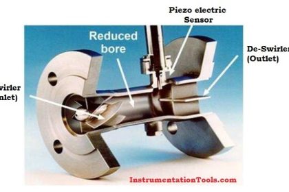
Piezoelectric Sensor
- Piezo element produces voltage output that is proportional to applied pressure.
- Whilst piezo ceramic material produces a high output it’s hawing limited operating temperature range (about 250° C).
- Lithium niobate (linbo3) piezoelectric material offers only medium output but operating temperature range is above 300° C.
- These type sensors are unsuitable for temp. below -40° C
- This sensor same like capacitive sensor.
Strain Gauge Sensor
- The vortex created by bluff body causes the body itself to be displaced by small amount of the order of 10µm.
- This elastic movement can be detected using strain gauges attached directly or indirectly to the bluff body.
- Movement of the body produces a change in resistance of the strain gauge.
- Main drawback is upper temperature limitation of strain gauge (about 120° C).
Ultrasonic Sensors
- Ultrasonic transmitter and receiver placed behind the bluff body.
- The vortex modulates the ultrasonic beam and the resultant output is the vortex signal.
- This sensor system has a good turn down ratio.
- The main problem associated with this technique is that extraneous sound sources can affect measurement.
The majority of vortex meter use piezoelectric or capacitance type sensor. to detect the pressure oscillation around the bluff body.
The strouhal number and bluff body width and the cross sectional area of the flow meter are all constants (which is defined as “K”) the equation becomes
Q = F/K
“K” factor can be defined as pulses per unit volume such as pulses per gallons, pulses per liter, pulses per cubic feet, therefore one can determine flow rate by counting the pulses per unit time.
Vortex frequencies range from one to thousands of pluses per second depending upon the flow viscosity the character of the process fluid and the size of meter.
Hints of Vortex Flow Meter
The pipe Reynolds number should be above 30,000 minimum. This means vortex meters can only be used on low viscosity liquids. High viscous fluids (>3 pa.s (30cp)) and slurries are not recommended applications. (higher viscous having head loss)
The vortex shedding meter provides a linear digital output signal without the use of separate transmitter or converters.
There is no drift because this is a frequency system
The calibration of the meter is virtually independent of the operating conditions (viscosity, density, pressure, temperature and so on) whether the meter is being used on gas or liquid.
Low pressure (low density) gases do not produce a strong enough pressure pulse, especially if fluid velocity are low (if use the meter will be poor and low flows will not be measurable.
Vortex meter accuracy is based on the known value of the meter factor (K- factor).
If you liked this article, then please subscribe to our YouTube Channel for Instrumentation, Electrical, PLC, and SCADA video tutorials.
You can also follow us on Facebook and Twitter to receive daily updates.
Read Next:
- Flow Meter K-factor Calculation
- How-to choose Thermowell
- PLC Conveyor Ladder Logic
- Strain Gauge Accelerometer
- Swirl Flow Meters Principle