PLC logic designed for efficient automation control of spray nozzle, fans, and puncher in industrial processes.
Disclaimer: This PLC programming example is for study purposes and to learn the ladder logic with simple applications.
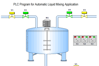
Control Spray Nozzle, Fans, and Puncher
Problem Statement:
Design a PLC ladder logic for the following application.
We are using one toggle switch and one sensor to control the Spray Nozzle, Dry Fans, and Puncher.
When an Object enters the booth, the Spray should start and continue for 10 seconds.
After that drying fans will turn ON for 10 seconds. Then Puncher will be activated to push the object.
Industrial Training Video
Instrumentation Tools provides you the free industrial training videos on the PLC, SCADA, and HMI.
This video explains the PLC program with a step-by-step approach to the given problem.
Digital Inputs
Start Button: I0.0
Sensor: I0.1
Digital Outputs
Spray Nozzle: Q0.0
Dry Fans: Q0.1
Puncher: Q0.2
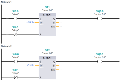
PLC Logic
Program Description
We have used the normally open contacts for the Start Button (I0.0) and Sensor (Q0.1).
We have used Normally Closed Contact for Spray Nozzle (Q0.0).
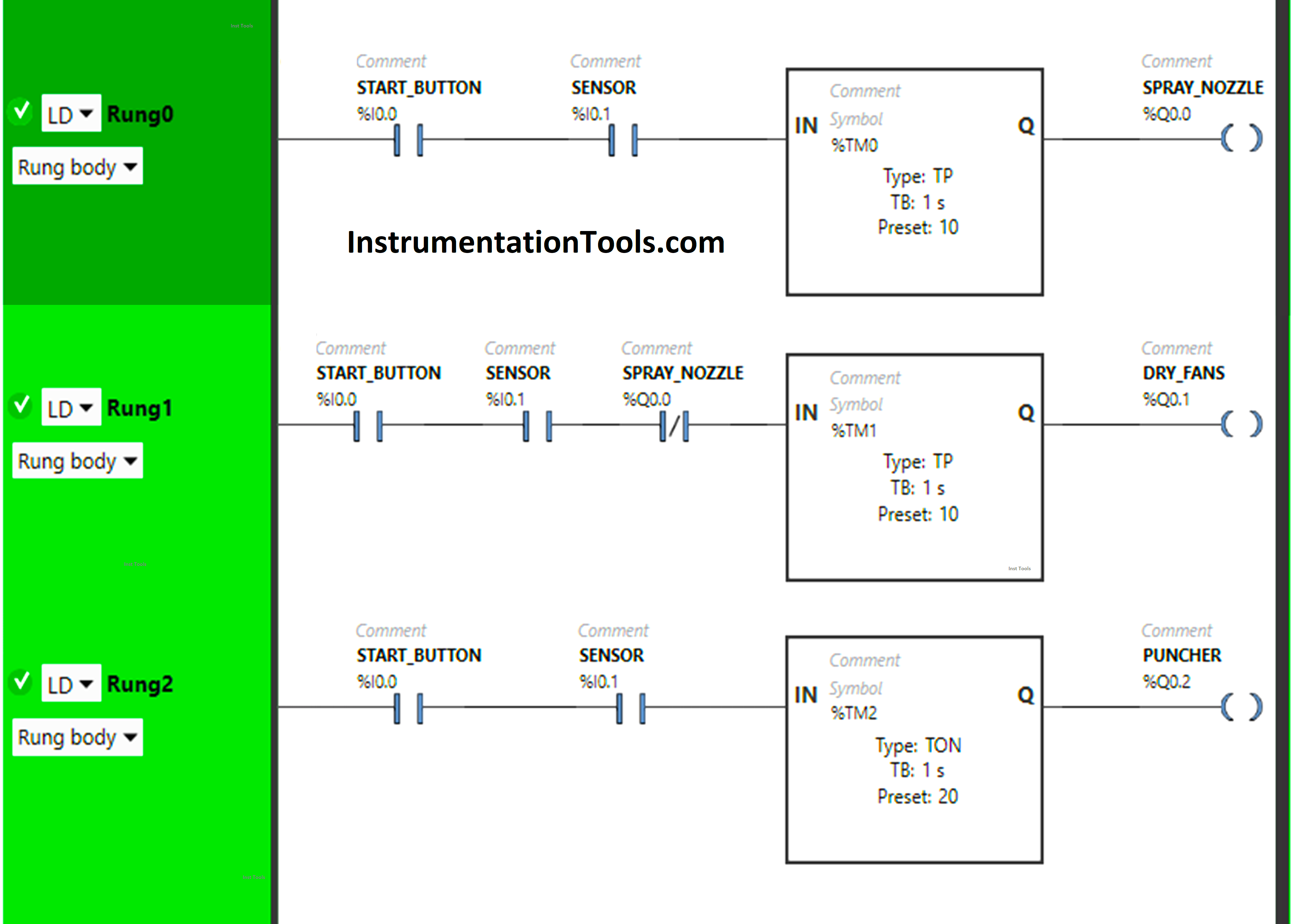
In Rung 0:
- Normally Open Contact is used for the Start Button (I0.0) and Sensor (I0.1) to Turn ON the output Spray Nozzle (Q0.0).
- Timer TP is used to Turn ON the output Spray Nozzle (Q0.0) for a limited time.
In Rung 1:
- Normally Open Contact is used for the Start Button (I0.0) and Sensor (I0.1) to Turn ON the output Dry Fans (Q0.1).
- Normally Closed Contact is used for the Spray Nozzle (Q0.0) to turn the output Dry Fans (Q0.1).
- Timer TP is used to Turn ON the output Dry Fans (Q0.1) for a limited time.
In Rung 2:
- Normally Open Contact is used for the Start Button (I0.0) and Sensor (I0.1) to Turn ON the output Puncher (Q0.2).
- Timer TON is used to delay the turning ON time of the output Puncher (Q0.1) for some time.
Simulation
Let us simulate our ladder logic to understand its response with inputs. We may shown some part of the logic or rungs instead of the complete program.
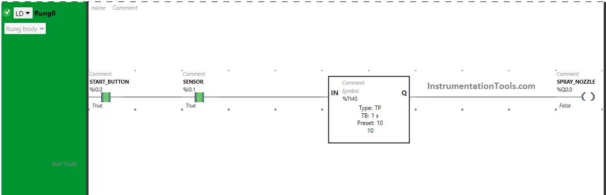
Rung 0:
When Start Button (I0.0) turns ON and Sensor (I0.1) gets activated or (Sensor detects an Object entering), the output Spray Nozzle (Q0.0) turns ON or (Spray Starts) as Normally Open Contacts used for Start Button (I0.0) and Sensor (Q0.1) will be in True State and allows the signal to turn ON the output Spray Nozzle (Q0.0).
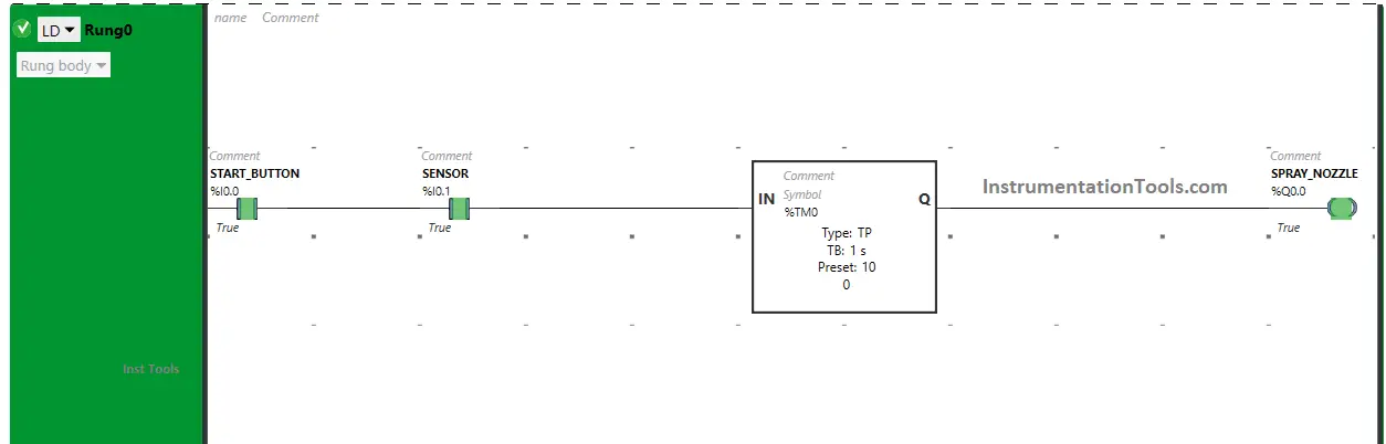
The output Spray Nozzle (Q0.0) will turn ON only for 10 seconds as Timer Function Block type TP is used to Turn ON the output Spray Nozzle (Q0.0) for a limited time. The time is set to 10 seconds. After 10 seconds, the output Spray Nozzle (Q0.0) will turn OFF.
Rung 1:
Also, When Start Button (I0.0) turns ON and Sensor (I0.1) gets activated or (Sensor detects an Object entering), the output Dry Fans (Q0.1) turns ON after 10 seconds or ( Drying Fans turns ON after 10 seconds) as in Rung0, when the output Spray Nozzle (Q0.0) turns ON, Normally Closed Contact used for Spray Nozzle (Q0.0) in Rung1 will be in True state and will not allow signal to flow through it.
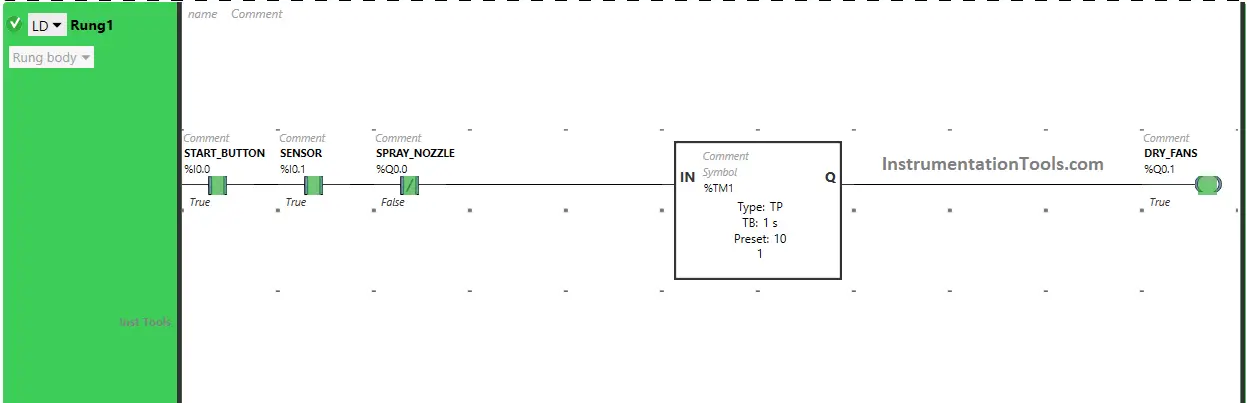
So, after 10 seconds, when the output Spray Nozzle (Q0.0) turns OFF in Rung0, the Normally Closed Contact used for Spray Nozzle (Q0.0) in Rung1 will be in a false state and will pass the signal to turn ON the output Dry Fans (Q0.1) after 10 seconds (i.e immediately when Spray Nozzle turns OFF).
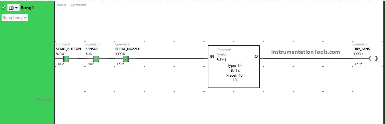
The output Dry Fans (Q0.1) will turn ON only for 10 seconds as Timer Function Block type TP is used to Turn ON the output Dry Fans (Q0.1) for a limited time. The time is set to 10 seconds. After 10 seconds, the output Dry Fans (Q0.1) will turn OFF.
Rung 2:
When the Start Button (I0.0) turns ON and Sensor (I0.1) gets activated or (Sensor detects an Object entering), the output Puncher (Q0.2) will turn ON after 20 seconds (i.e immediately when the output Dry Fans (Q0.1) turns OFF) as Timer Function Block TON is used to delay the turning ON time of the output Puncher (Q0.2).
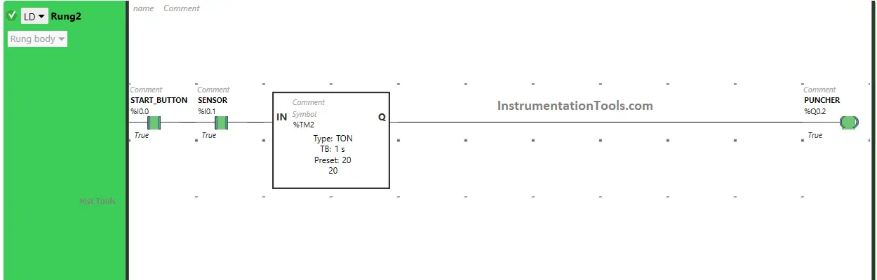
The time is set to 20 seconds. After 20 seconds, the output Puncher (Q0.2) will turn ON.
If you liked this article, please subscribe to our YouTube Channel for PLC and SCADA video tutorials.
You can also follow us on Facebook and Twitter to receive daily updates.
Read Next:
- Ladder Diagram Control using Timers
- PLC Programming for Elevator Stop Logic
- PLC Programming on Bottle Line Control
- Conveyor and Puncher PLC Programming
- Batch Mixing PLC Ladder Logic Program