The direction of action for a loop controller – either direct or reverse – at first seems like a very simple concept.
It certainly is fundamental to the comprehension of any control strategy containing PID loop controllers, but this seemingly simple concept harbors an easy-to-overlook fact causing much confusion for people as they begin to analyze any control strategy where a loop controller receives a remote setpoint signal from some other device, most notably in cascade and ratio control strategies.
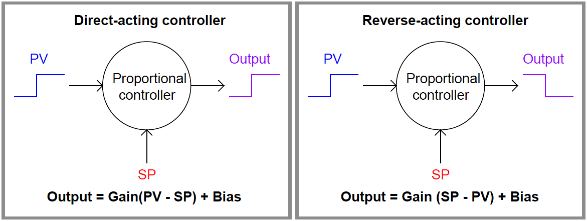
A direct-acting loop controller is defined as one where the output signal increases as the process variable signal increases. A reverse-acting controller is defined as one where the output signal decreases as the process variable signal increases.
Both types of action are shown here:
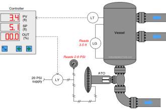
Let us apply this concept to a realistic application, in this case the control of temperature in a steam-heated chemical reactor vessel:
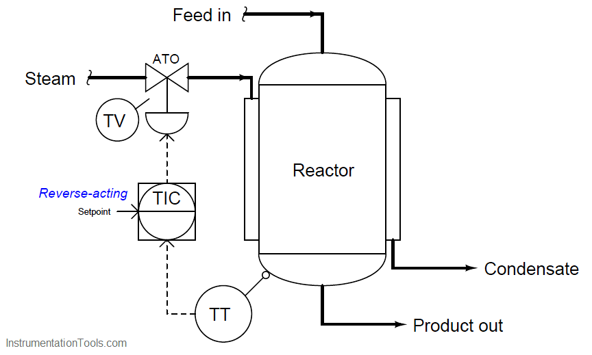
As the reactor vessel’s temperature increases, we need the temperature controller (TIC) to reduce the amount of hot steam entering the jacket in order to stabilize that temperature.
Since the steam control valve is air-to-open (ATO), this means we need the controller to output a decreasing signal as the process variable (temperature) signal increases.
This, by definition, is a reverse-acting controller. This example also showcases the utility of the problem-solving technique known as a “thought experiment,” whereby we imagine a certain condition changing (in this case, the reactor temperature increasing) and then we mentally model the desired response of the system (in this case, closing the steam valve) in order to determine the necessary controller action.
So far, this example poses no confusion. But suppose we were to perform another thought experiment, this time supposing the setpoint signal increases rather than the reactor temperature increases. How will the controller respond now?
Many people will conclude that the controller’s output signal will once again decrease, because we have determined this controller’s action to be reverse, and “reverse” implies the output will go the opposite direction as the input.
However, this is not the case: the controller output will actually increase if its setpoint signal is increased. This, in fact, is precisely how any reverse-acting controller should respond to an increase in setpoint.
The reason for this is evident if we take a close look at the characteristic equation for a reverse acting proportional controller. Note how the gain is multiplied by the difference between setpoint and process variable.
Note how the process variable has a negative sign in front of it, while setpoint does not.
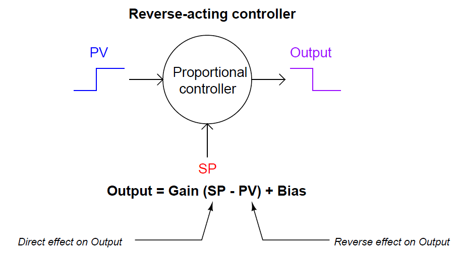
An increase in process variable (PV) causes the quantity inside the parentheses to become more negative, or less positive, causing the output to decrease toward 0%.
Conversely, an increase in setpoint (SP) causes the quantity inside the parentheses to become more positive, causing the output to increase toward 100%.
This is precisely how any loop controller should respond: with the setpoint having the opposite effect of the process variable, because those two quantities are always being subtracted from one another in the proportional controller’s equation.
Where people get confused is the single label of either “direct” or “reverse” describing a controller’s action. We define a controller as being either “direct-acting” or “reverse-acting” based on how it responds to changes in process variable, but it is easy to overlook the fact that the controller’s setpoint input must necessarily have the opposite effect. What we really need is a way to more clearly denote the respective actions of a controller’s two inputs than a single word.
Thankfully, such a convention already exists in the field of electronics, where we must denote the “actions” of an operational amplifier’s two inputs.
In the case of an opamp, one input has a direct effect on the output (i.e. a change in signal at that input drives the output the same direction) while the other has a reverse effect on the output (i.e. a change in signal at that input drives the output in the opposite direction).
Instead of calling these inputs “direct” and “reverse”, however, they are conventionally denoted as non-inverting and inverting, respectively. If we draw a proportional controller as though it were an opamp, we may clearly denote the actions of both inputs in this manner:
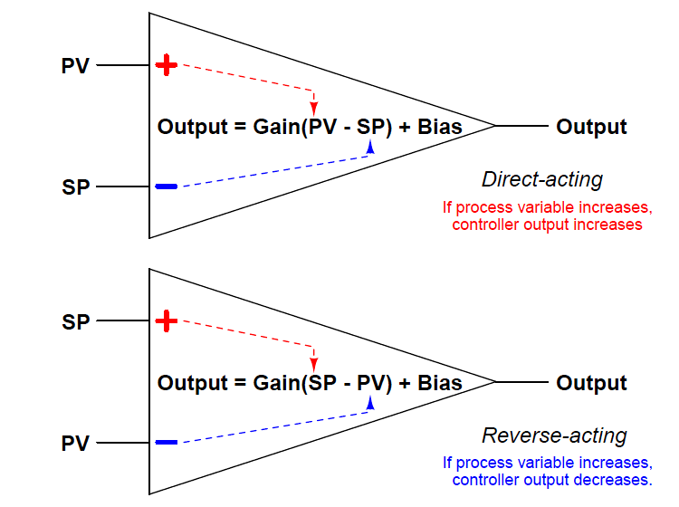
I strongly recommend people to label the loop controllers in any complex control strategy in the same manner, with “+” and “−” labels next to the PV and SP inputs for each controller, in order to unambiguously represent the effects of each signal on a controller’s output. This will be far more informative, and far less confusing, than merely labeling each controller with the word “direct” or “reverse”.
Let us return to our example of the steam-heated reactor to apply this technique, labeling the reverse-acting controller’s process variable input with a “−” symbol and its setpoint input with a “+” symbol:
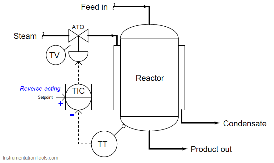
With these labels in place we can see clearly how an increase in temperature going into the “−” (inverting) input of the temperature controller will drive the valve signal down, counter-acting the change in temperature and thereby stabilizing it.
Likewise, we can see clearly how an increase in setpoint going into the “+” (noninverting) input of the temperature controller will drive the valve signal up, sending more steam to the reactor to achieve a greater temperature.
While this technique of labeling the PV and SP inputs of a loop controller as though it were an operational amplifier is helpful in single-loop controller systems, it is incredibly valuable when analyzing more complex control strategies where the setpoint to a controller is a live signal rather than a static value set by a human operator.
In fact, it is for this very reason that many people do not begin to have trouble with this concept until they begin to study cascade control, where one controller provides a live (“remote”) setpoint value to another controller.
Up until that point in their study, they never rarely had to consider the effects of a setpoint change on a control system because the setpoint value for a single-loop controller is usually static.
Also Read : Cascade Control


GOOD
hi bradway
thanks very much
we have a problem in our dcs3000 yokogawa
our cards AAI835 and AAI135 Analog cards of dcs damaged very much
wha is the problem do you think?
ground, kind of cards,??