Inst ToolsInst ToolsInst Tools
  • Courses
  • Automation
    • PLC
    • Control System
    • Safety System
    • Communication
    • Fire & Gas System
  • Instrumentation
    • Design
    • Pressure
    • Temperature
    • Flow
    • Level
    • Vibration
    • Analyzer
    • Control Valve
    • Switch
    • Calibration
    • Erection & Commissioning
  • Interview
    • Instrumentation
    • Electrical
    • Electronics
    • Practical
  • Q&A
    • Instrumentation
    • Control System
    • Electrical
    • Electronics
    • Analog Electronics
    • Digital Electronics
    • Power Electronics
    • Microprocessor
  • Request
Search
  • Books
  • Software
  • Projects
  • Process
  • Tools
  • Basics
  • Formula
  • Power Plant
  • Root Cause Analysis
  • Electrical Basics
  • Animation
  • Standards
  • 4-20 mA Course
  • Siemens PLC Course
Reading: Vibrating Fork Level Switch Working Animation
Share
Font ResizerAa
Inst ToolsInst Tools
Font ResizerAa
  • Courses
  • Design
  • PLC
  • Interview
  • Control System
Search
  • Courses
  • Automation
    • PLC
    • Control System
    • Safety System
    • Communication
    • Fire & Gas System
  • Instrumentation
    • Design
    • Pressure
    • Temperature
    • Flow
    • Level
    • Vibration
    • Analyzer
    • Control Valve
    • Switch
    • Calibration
    • Erection & Commissioning
  • Interview
    • Instrumentation
    • Electrical
    • Electronics
    • Practical
  • Q&A
    • Instrumentation
    • Control System
    • Electrical
    • Electronics
    • Analog Electronics
    • Digital Electronics
    • Power Electronics
    • Microprocessor
  • Request
Follow US
All rights reserved. Reproduction in whole or in part without written permission is prohibited.
Inst Tools > Blog > Animation > Vibrating Fork Level Switch Working Animation

Vibrating Fork Level Switch Working Animation

Last updated: January 12, 2018 6:02 pm
Editorial Staff
Animation Level Measurement
2 Comments
Share
1 Min Read
SHARE
        Vibrating Fork Level Switch Working Animation
Vibrating Fork Level Switch Working Animation

Animation Credits : KANSAI Automation

Working Principle: 
 
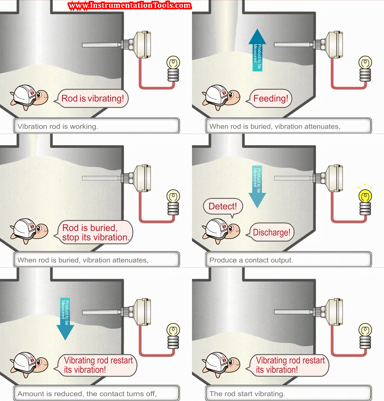
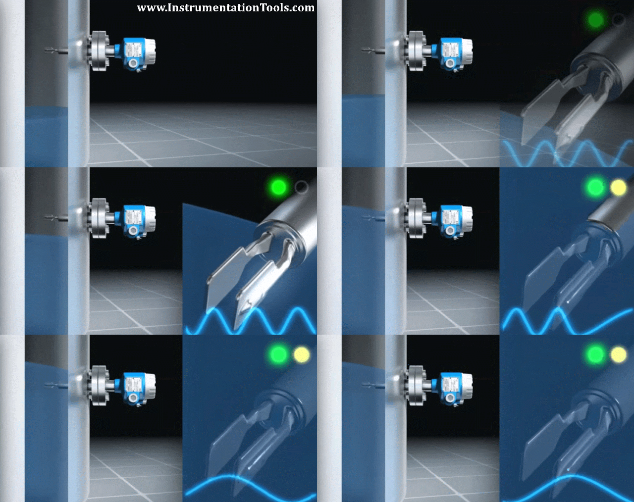
The vibrating fork type level sensor works on the principle of tuning forks. There is a Piezo ceramic crystals located inside the fork assembly. On the application of voltage, the crystals oscillate at the natural frequency of the fork assembly. This frequency is continuously monitored by the internal electronic circuitry.

When the fork comes in contact with liquids/solid material, the frequency slightly changes, and this change in frequency is sensed by the electronic circuit which in turn send out a signal. This signal is processed to give out as a relay output either N.O or N.C. signal which in turn indicates Level signal either Low or High depends on application.
Vibrating Level Switch Working Principle

Animation Credits : Endress Hauser
Don't Miss Our Updates
Be the first to get exclusive content straight to your email.
We promise not to spam you. You can unsubscribe at any time.
Invalid email address
You've successfully subscribed !

Continue Reading

How a Level Switch Works
Tuning Fork Level Switch Principle
Optical Level Switch Working Principle
Guided Wave Radar Level Sensor Pressure and Temperature Effects
Basics of DP Transmitter Suppression and Elevation
Cable Float Level Switch Working Principle
Share This Article
Facebook Whatsapp Whatsapp LinkedIn Copy Link
Share
2 Comments
  • Babu says:
    July 14, 2015 at 1:45 am

    Mind blowing Animations. Very attractive and easy to learn.

    Reply
  • hanumanth says:
    May 22, 2016 at 11:14 am

    very practical

    Reply

Leave a Reply Cancel reply

Your email address will not be published. Required fields are marked *

Stay Connected

128.3kFollowersLike
69.1kFollowersFollow
210kSubscribersSubscribe
38kFollowersFollow

Categories

Explore More

Types of Pneumatic Actuators Animation
All About Instrumentation Impulse Lines
Servo Operated Float Level Measurement
Four Way Solenoid Valve Working Principle
Wrong Installation of Horn Type Radar Level Transmitter on Sloping Tank
Digital Building Blocks – GATES
In-Line Flow Switch Working Principle and Animation
Closed Tank Level Measurement using DP Transmitters

Keep Learning

Wire Guided Float Detectors

Inductively Coupled Wire Guided Float Detectors

Guided wave radar Measurement Principle

Guided Wave Radar – Principle, Limitations, Installation

Tank Gauging Measurement

Purpose of Tank Gauging Level Measurement

Open-Tank-DP-Level-Transmitter-with-Zero-Suppression-Calibration

DP Level Transmitter with Zero Suppression Calibration

Transistor as Switch Working Animation

How a Transistor Switch Works

Displacer interface level measurement Calibration

Displacer Interface Level Measurement

Tilt Level Switch Theory

Tilt Level Switch Working Principle

Level Calculation with Remote Seals

Level Calculation with Remote Seals

Learn More

Liapunov’s Stability Analysis

Direct Method & Constructing of Liapunov for the Linear & Non-Linear System

Wave Trap in Power Line carrier Communication

What is a Wave Trap? – Power Line Carrier Communication

Electrical Machines Questions and Answers

Rotating Magnetic Field Multiple Choice Questions

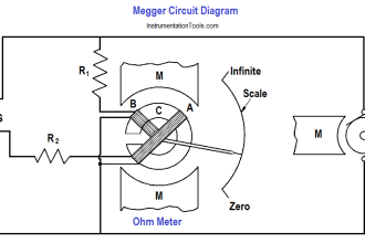
Megger Circuit Diagram

Multimeter & Megger Principle

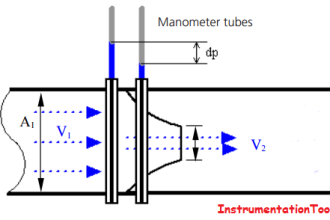
How a Δp flow meters works

What is Differential Pressure Flow Meter?

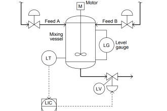
level control system

Practical Process Control System Questions & Answers – 10

Instrumentation Control Systems

What is Instrumentation Control System ?

capacitor-filter

Capacitor Filter Working Principle

Menu

  • About
  • Privacy Policy
  • Copyright

Quick Links

  • Learn PLC
  • Helping Hand
  • Part Time Job

YouTube Subscribe

Follow US
All rights reserved. Reproduction in whole or in part without written permission is prohibited.
Welcome Back!

Sign in to your account

Username or Email Address
Password

Lost your password?