Measurement Principle
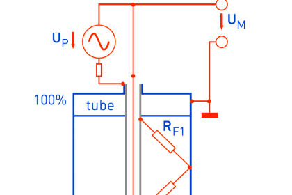
Guided wave radar (GWR) technology is based on the Time Domain Reflectometry (TDR) principle. Low power nanosecond‐pulses are guided along with a probe submerged in the process media. When a pulse reaches the surface of the material it is measuring, part of the energy is reflected back to the transmitter, and the time difference between the generated and reflected pulse is converted into a distance from which the total level or interface level is calculated.
The speed of travel of the pulse is impacted by the dielectric of the medium. This change in travel time is predictable and allows compensation for the measurement to be accomplished. The reflectivity of the product is a key parameter for measurement performance. A high dielectric constant (DC) of the media gives a better reflection and a longer measuring range.

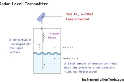
Figure 1: GWR Typical interface level reflection
When an interface level of two immiscible layers should be measured, the first fluid should have a lower dielectric. The reflection from this first low dielectric fluid is weak. This permits the rest of the signal to detect the interface between these two fluids. Less than 5% of the signal is reflected back to the transmitter for a fluid with a dielectric of 2 (e.g. oil).
Interface measurement accuracy depends on the upper product dielectric and a distinct interface (low emulsion layer of few mm) between the two fluids.
Limitations
While guided wave radar works in many conditions, some precautions need to be taken with respect to probe choice. Several probe styles are available and the application, length, and mounting restrictions influence their choice. Unless a coax‐style probe is used, probes should not be in direct contact with a metallic object, as that will impact the signal.
If the application tends to be sticky or coat, then only single lead probes should be used. Single lead probes are preferred when there is a risk of contamination (because the coating can result in the product bridging across the two leads for twin versions or between the inner lead and outer pipe for the coaxial probes, and may cause erroneous level readings).
For viscous or sticky applications, PTFE probes are recommended to facilitate product flow. Periodic cleaning may also be required. Maximum error due to coating is 1–10% depending on probe type, dielectric constant, coating thickness and coating height above the product surface. The presence of oil‐film on the single probe will not have any effect.
Some advanced GWRs on the market have advanced diagnostics, with the ability to detect build‐up on the probe. This gives an indication of how good the surface signal is compared to the noise, and when to clean the probe (predictive maintenance).
GWR can be used on cryogenic applications (e.g. −196°C) with the recommendation of the coaxial probe. Proper insulation may be required to reduce ice formation on the upper part (e.g. insulate the nozzle).
GWR measurement in foamy applications depends on the foam properties: light and airy or dense and heavy, high or low dielectrics, etc. If the foam is conductive and dense, the transmitter may measure the surface of the foam. If the foam is less conductive, the microwaves may penetrate the foam and measure the liquid surface. This type of application should be considered on a case by case basis. Depending on foam properties, GWR may detect the foam/liquid interface or the top of the foam or the top of the liquid.
GWR is not suitable for the water–sand interface. Since the sand is embedded in water, which is a high dielectric media (DC = 80), the transmitter can only see the water. The same is true for all media that are dissolved in water.
Different parameters (factors) affect the echo and therefore the maximum measuring range differs depending on application according to:
- disturbing objects close to the probe
- media with higher dielectric constant gives a better reflection and allows a longer measuring range
- surface foam and particles in the tank atmosphere may affect measuring performance
- heavy coating or contamination on the probe should be avoided since it can reduce the measuring range and might cause erroneous level readings.

Figure 2: GWR interface level measurement
When the interface will be measured, the criteria according to Figure 3 should be fulfilled:

Figure 3: GWR Interface measurement dielectric criteria
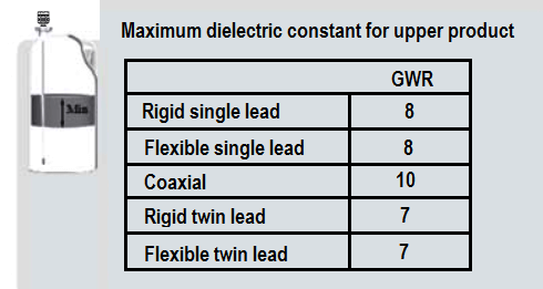
Figure 4: GWR Maximum dielectric constant vs technology.
The maximum allowable upper product thickness/measuring range is primarily determined by the dielectric constants of the two liquids.
An example of the maximum upper product thickness for the flexible single probe is presented in Figure 5. However, characteristics can vary between the different applications.

Figure 5: GWR Maximum upper product thickness
Emulsion/rag layer
Emulsions/foam above a few centimeters disrupt the interface measurement. The results vary with the fluid mix. In many cases, the interface is measured at the top of the emulsion layer.
Emulsion layers above a few centimeters cannot be measured with the GWR principle. This is due to the emulsion dielectric stochastic repartition and the emulsion bubble composition. If the emulsion layer is greater than a few centimeters only the top of the upper layer can be detected.
Sometimes emulsion can be formed of a mixture of fine solids combined with emulsified oil and water, sometimes including multiple components. Stable liquid emulsion and solid particles trigger rapid emulsion layer growth.
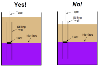
The more particles are present, the larger such an emulsion is. Although applications with emulsions are difficult for GWR measurement, the usage of a stilling well can help to achieve better product separation and therefore more accurate measurements.
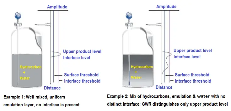


Figure 6: GWR interface measurement in the vessel with emulsion
Selection
GWR provides accurate and reliable interface measurements and can be used in a wide variety of applications. It is a top‐down, direct measurement as it measures the distance to the product surface.
GWR should be considered for clean liquid–liquid interface and/or clean liquid–gas interface.
GWR interface measurement with emulsion, foam, fluid buildup or crystallization is not possible (deposit causes false reading).
GWR level instrument accuracy is a function of the liquid dielectric constant. Care should be taken to determine the dielectric constants of the fluids being measured over their full range of possible compositions and operating conditions.
The vessel internals e.g. supports and reinforcement should not be at the vicinity of the level measurement device or in the radar path.
GWR requires a relatively flat fluid surface. If surface is turbulent then a Stilling Well should be considered.
For long probes, the lower probe end should be fitted with an additional stainless steel cylinder with fixing eye to ensure an adequate fixing to the bottom of the vessel.
GWR installed in a sensor cage or standpipe should never be in contact with the cage/standpipe internals. Centring disk may be used. The centring disk should provide isolation between the probe and the cage/standpipe internals.
GWR sensor cage/stand pipe measuring range should be carefully studied. For a side–side sensor cage/stand pipe the maximum measuring range should be between the middle (axe) of the upper and the lower tapping connection.
A key advantage of radar is that changes in pressure, temperature, and most vapour space conditions have no impact on the accuracy of its level measurements. Moreover, no compensation is necessary for changes in dielectric, conductivity, or density of the fluid.
Changing density is one of the major issue is when measuring level or interface using older technologies, such as displacers; they are more likely to happen due to changes in process or ambient conditions, and thus have more influence on the reliability and accuracy of density based technologies..
n addition, radar devices have no moving parts, so maintenance is minimal. GWR is easy to install and enables simple replacement of older technologies, even while there is liquid in the tank.
Installation
Direct measurements on the top of the tank (flanges connection)
Below are recommendations for the nozzle configuration and dimensions for flanged installations on top of the tank/vessel.

Table 1: GWR nozzle diameter
Chambers with a diameter of less than 7.62 cm can cause problems with build‐up and might make it difficult to avoid contact between the chamber wall and probe.
Chambers provide a fixed view of the level in a vessel. Thus, when the level drops below or rises above the chamber, it will not be seen in the chamber. The effective measurement range of a chamber is the area between the taps.

Figure 7: GWR possible error chambers measurement
Chamber installation and sizing
The location of the chamber should be as close to area of measurement as possible. If the chamber is further away, the fluid inside it is less like the fluid in the vessel. More distance gives more time for the fluid to cool (or heat up in cryogenic applications). Cooler fluid will be more viscous and dense.
More viscous fluid will not respond as quickly and in extreme cases, can completely plug the chamber. Larger connections between the vessel and the chamber will enhance flow‐through of the fluid and allow fresh fluid to move through the chamber more easily and more closely resemble the material in the vessel.
If the density in the chamber is lower than the density of the fluid in the vessel, it may actually appear to ‘shrink’ and cause the level measurement to be lower in the vessel than it actually is, especially if fluid movement is stagnant.

Figure 8: GWR chamber installation and sizing
Match product level in tank and chamber
Below are examples of cases that might occur in field conditions.

Figure 9: GWR Case 1 – Difference in product-specific gravity (SG)

Figure 10: GWR Case 2 – Lack of circulation in the chamber
Level and interface applications
Measurement of level and interface in a chamber should be avoided as the lack of fluid flow will not provide representative measurements.
However, chambers are often used for interface measurements between oil and water. In cases where it is the only way to get a measurement, multiple connections to chamber will help to enhance fluid flow. The additional crossover connections should be located near the more critical measurement areas.
In these applications, there should be good flow‐through of both the top and bottom fluid for the interface measurement to be tracked. Care should be taken to avoid having a layer of fluid trapped in the chamber.
Interface measurements should assess the dielectric constant of both layers to properly configure the device for the intended level application. Specific configuration parameters might require adjustment once the device has been commissioned.

Figure 11: GWR chamber with multiple connections
Fully submerged interface applications
A submerged interface application is one where the upper portion of the probe is in oil or a similar fluid and the interface between the upper fluid and lower fluid is the desired measurement. Often this measurement is done with the GWR mounted in a chamber/cage. This is called a flooded chamber.
A single lead probe should always be used for this application as this provides the most distinct reference pulse. Ideally, there should be no air gap present at the top of the probe.
However, air is often trapped in the chamber. If there is an air pocket, then it creates an offset in the measurement reading due to the difference in the speed of travel of the microwaves in the air space compared to the upper fluid.
For example, if the device is configured with oil as the upper fluid with dielectric constant of 2, the offset error will be 30% of the size of the air pocket (that is, a 15.7 in. (40 cm) air pocket creates a 4.7 in. (12 cm) offset error to the reading).
There are several options available to overcome the error introduced due to the air pocket:
If process safety allows it, a vent can be included in the top of the chamber that allows the air to be removed. This vent can be piped back to process. A flushing ring can be installed between the GWR flange and the chamber flange to accommodate this.

Figure 12: GWR fully submerge air pocket
If the air pocket is small and is within the upper blind zone of the device, the Upper Null Zone can be configured to block any potential incorrect reading of the surface.
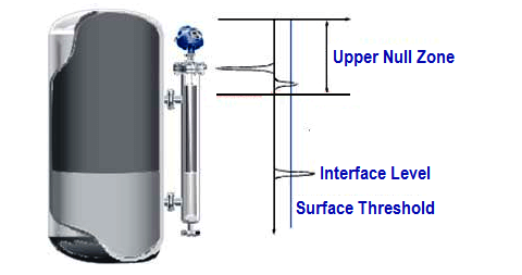
Figure 13: GWR fully submerge air pocket echo
Interface measurements in vessels
The most common interface application in vessels implies measurements of both upper product level and interface level.
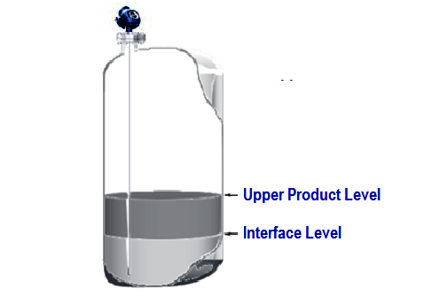
Figure 14: GWR interface measurement in vessel
Though not very common, fully submerged vessel interface applications can be possible too. A good example of such application are desalters and inverted interface measurements.
Inverted interface measurements
The previous examples cover situations when the upper product has a lower DC than the lower one. However, sometimes there are applications where product disposition is inverted: the high dielectric product lies on top of the low dielectric one, which makes top‐down measurement impossible for GWR.
In this case, the GWR mounting position is inverted so that it is installed at the bottom of the tank. For applications where there may be some solids or slushy deposits at the bottom of the vessel, it is advisable to put a flushing connection in the mounting nozzle to allow occasional cleaning.

Figure 15: GWR interface measurement in the vessel with lower DC upper
Configuration routine is the same as for standard interface measurements using interface with submerged probe mode.
Dielectric constants have to be set according to product separation. Upper product means the one that is closer to the tank bottom.
When installing GWR on the tank bottom, there is no limit of probe types to be used. Flexible probes need to be attached to the tank roof. This can be done by following the same guidelines, provided for standard installations.
Calibration and Configuration
The actual upper media DC value is known. The configuration needs to include the actual DC value (at the factory or at the site). If the actual upper DC is not known in a range of 20% around the actual measure, the accuracy will be impacted.
Above this 20% value, it is recommended to perform a site/field calibration to improve the measurement accuracy.
Source: International Association of Oil & Gas Producers
Acknowledgments: IOGP Instrumentation and Automaton Standards Subcommittee (IASSC), BG Group, BP, Endress + Hauser, Emerson, Honeywell, Krohne, Petrobras, PETRONAS Carigali Sdn Bhd, Repsol, Siemens, Statoil, Total, Vega, Yokogawa.
Read Next:
- Guided-wave Radar Animation
- Displacer Level Measurement
- Non Contact RADAR Level Transmitter
- Contact Type Guided Wave Radar
- Design of Level Sensors on Tanks