Inst ToolsInst ToolsInst Tools
  • Courses
  • Automation
    • PLC
    • Control System
    • Safety System
    • Communication
    • Fire & Gas System
  • Instrumentation
    • Design
    • Pressure
    • Temperature
    • Flow
    • Level
    • Vibration
    • Analyzer
    • Control Valve
    • Switch
    • Calibration
    • Erection & Commissioning
  • Interview
    • Instrumentation
    • Electrical
    • Electronics
    • Practical
  • Q&A
    • Instrumentation
    • Control System
    • Electrical
    • Electronics
    • Analog Electronics
    • Digital Electronics
    • Power Electronics
    • Microprocessor
  • Request
Search
  • Books
  • Software
  • Projects
  • Process
  • Tools
  • Basics
  • Formula
  • Power Plant
  • Root Cause Analysis
  • Electrical Basics
  • Animation
  • Standards
  • 4-20 mA Course
  • Siemens PLC Course
Reading: Types of Pneumatic Actuators Animation
Share
Notification Show More
Font ResizerAa
Inst ToolsInst Tools
Font ResizerAa
  • Courses
  • Design
  • PLC
  • Interview
  • Control System
Search
  • Courses
  • Automation
    • PLC
    • Control System
    • Safety System
    • Communication
    • Fire & Gas System
  • Instrumentation
    • Design
    • Pressure
    • Temperature
    • Flow
    • Level
    • Vibration
    • Analyzer
    • Control Valve
    • Switch
    • Calibration
    • Erection & Commissioning
  • Interview
    • Instrumentation
    • Electrical
    • Electronics
    • Practical
  • Q&A
    • Instrumentation
    • Control System
    • Electrical
    • Electronics
    • Analog Electronics
    • Digital Electronics
    • Power Electronics
    • Microprocessor
  • Request
Follow US
All rights reserved. Reproduction in whole or in part without written permission is prohibited.
Inst Tools > Blog > Animation > Types of Pneumatic Actuators Animation

Types of Pneumatic Actuators Animation

Last updated: March 21, 2019 11:38 pm
Editorial Staff
Animation Control Valves How It Works
No Comments
Share
3 Min Read
SHARE

A pneumatic control valve actuator converts energy (typically in the form of compressed air) into mechanical motion. The motion can be rotary or linear, depending on the type of actuator.

Types of Pneumatic Actuators Animation

Pneumatic Actuators Types Animation

A Pneumatic actuator mainly consists of a piston or a diaphragm which develops the motive power. It keeps the air in the upper portion of the cylinder, allowing air pressure to force the diaphragm or piston to move the valve stem or rotate the valve control element.

Valves require little pressure to operate and usually double or triple the input force. The larger the size of the piston, the larger the output pressure can be. Having a larger piston can also be good if air supply is low, allowing the same forces with less input.

These pressures are large enough to crush objects in the pipe. On 100 kPa input, you could lift a small car (upwards of 1,000 lbs) easily, and this is only a basic, small pneumatic valve. However, the resulting forces required of the stem would be too great and cause the valve stem to fail.

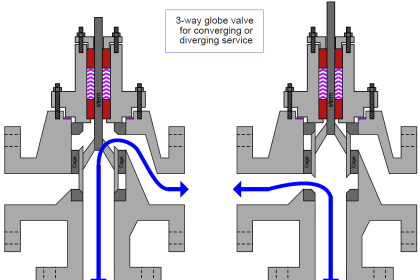
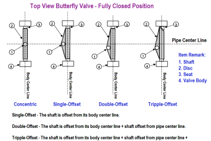
This pressure is transferred to the valve stem, which is connected to either the valve plug (see plug valve), butterfly valve etc. Larger forces are required in high pressure or high flow pipelines to allow the valve to overcome these forces, and allow it to move the valves moving parts to control the material flowing inside.

The valves input is the “control signal.” This can come from a variety of measuring devices, and each different pressure is a different set point for a valve. A typical standard signal is 20–100 kPa.

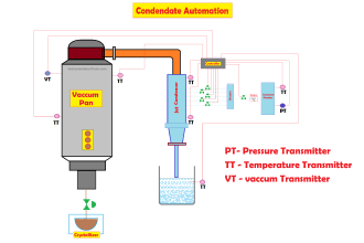
For example, a valve could be controlling the pressure in a vessel which has a constant out-flow, and a varied in-flow (varied by the actuator and valve).

A pressure transmitter will monitor the pressure in the vessel and transmit a signal from 20–100 kPa. 20 kPa means there is no pressure, 100 kPa means there is full range pressure (can be varied by the transmitters calibration points).

As the pressure rises in the vessel, the output of the transmitter rises, this increase in pressure is sent to the valve, which causes the valve to stroke downward, and start closing the valve, decreasing flow into the vessel, reducing the pressure in the vessel as excess pressure is evacuated through the out flow. This is called a direct acting process.

Articles You May Like :

Capacitance Level Sensor

Instrument Air Manifold

What is Ball Valve ?

Valve Actuators Questions

Solenoid Actuated Valves

Don't Miss Our Updates
Be the first to get exclusive content straight to your email.
We promise not to spam you. You can unsubscribe at any time.
Invalid email address
You've successfully subscribed !

Continue Reading

Control Valve Preventive Maintenance
Inherent vs Installed Control Valve Flow Characteristics
Difference between Rotary Shaft Valves and Sliding Stem Control Valves
Complementary Control Valve Sequence
What is Complementary Split Range Control (CSRC)?
ON OFF Valve Preventive Maintenance and Testing Procedure
Share This Article
Facebook Whatsapp Whatsapp LinkedIn Copy Link
Share
Leave a Comment

Leave a Reply Cancel reply

Your email address will not be published. Required fields are marked *

Stay Connected

128.3kFollowersLike
69.1kFollowersFollow
210kSubscribersSubscribe
38kFollowersFollow

Categories

Explore More

What is Needle Valve ?
Differential Pressure Switch Working Principle
Cavitation Test Setup
Safety Relief Valve Material Selection
What is an Unloading Valve? – Types, Principle
Over Pressure cases for Pressure Relief Valve Sizing
Ball Valve Material Selection
Basic Steps and Procedure for the Repair of Control Valve

Keep Learning

Control Valves Classification

Classification of Control Valves

What is Swing Check Valve ?

Vortex Flow Meter Animation

Basic Working Principle of Vortex Flowmeter

Metal Seated Ball Valves

Metal Seated Valves and Soft Seated Valves : Differences

Pneumatic Valves Questions & Answers

Pneumatic Valves Questions & Answers

Valve stem travel

Control Valves Mechanical Friction Problems

Averaging Pitot Tube Working Principle

Pitot Tube Working Principle

Transistor as Switch Working Animation

How a Transistor Switch Works

Learn More

PLC Latching circuit Animation

What is Seal-in Circuit ?

Power Electronics Objective Questions

Thyristor Gating Circuits Objective Questions

PLC Automatic Irrigation System Ladder Logic Project

PLC Automatic Irrigation System

Difference Between Modbus TCP IP and Profinet

Difference Between Modbus TCP IP and Profinet

Stripping tower unit

Process Control High Level Alarm Fault Analysis

Studio 5000 Logix Emulate

Simulation of Studio 5000 and FactoryTalk View Studio

CNC Milling versus CNC Turning

CNC Milling versus CNC Turning – Which is the Best Option?

Digital Control Systems

Compensation Techniques : Control Systems

Menu

  • About
  • Privacy Policy
  • Copyright

Quick Links

  • Learn PLC
  • Helping Hand
  • Part Time Job

YouTube Subscribe

Follow US
All rights reserved. Reproduction in whole or in part without written permission is prohibited.
Welcome Back!

Sign in to your account

Username or Email Address
Password

Lost your password?