Inst ToolsInst ToolsInst Tools
  • Courses
  • Automation
    • PLC
    • Control System
    • Safety System
    • Communication
    • Fire & Gas System
  • Instrumentation
    • Design
    • Pressure
    • Temperature
    • Flow
    • Level
    • Vibration
    • Analyzer
    • Control Valve
    • Switch
    • Calibration
    • Erection & Commissioning
  • Interview
    • Instrumentation
    • Electrical
    • Electronics
    • Practical
  • Q&A
    • Instrumentation
    • Control System
    • Electrical
    • Electronics
    • Analog Electronics
    • Digital Electronics
    • Power Electronics
    • Microprocessor
  • Request
Search
  • Books
  • Software
  • Projects
  • Process
  • Tools
  • Basics
  • Formula
  • Power Plant
  • Root Cause Analysis
  • Electrical Basics
  • Animation
  • Standards
  • 4-20 mA Course
  • Siemens PLC Course
Reading: Optical Level Switch Working Principle
Share
Font ResizerAa
Inst ToolsInst Tools
Font ResizerAa
  • Courses
  • Design
  • PLC
  • Interview
  • Control System
Search
  • Courses
  • Automation
    • PLC
    • Control System
    • Safety System
    • Communication
    • Fire & Gas System
  • Instrumentation
    • Design
    • Pressure
    • Temperature
    • Flow
    • Level
    • Vibration
    • Analyzer
    • Control Valve
    • Switch
    • Calibration
    • Erection & Commissioning
  • Interview
    • Instrumentation
    • Electrical
    • Electronics
    • Practical
  • Q&A
    • Instrumentation
    • Control System
    • Electrical
    • Electronics
    • Analog Electronics
    • Digital Electronics
    • Power Electronics
    • Microprocessor
  • Request
Follow US
All rights reserved. Reproduction in whole or in part without written permission is prohibited.
Inst Tools > Blog > Level Measurement > Optical Level Switch Working Principle

Optical Level Switch Working Principle

Last updated: March 30, 2019 5:43 pm
Editorial Staff
Level Measurement Switches
1 Comment
Share
1 Min Read
SHARE

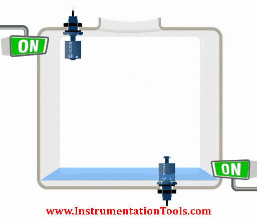
Optical level switch uses the principle of total reflection in a prism. Reflection or penetration, is the basis of the level alarm output. When the sensor is surrounded by air, the angle of incidence is greater than the critical angle and thus total reflection occurs.

Optical Level Switch

Optical Level Switch Working Principle

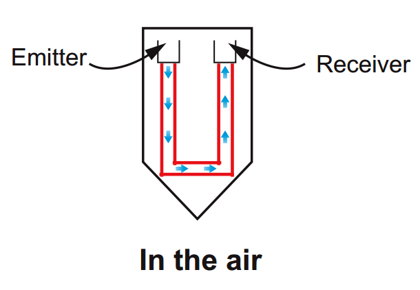
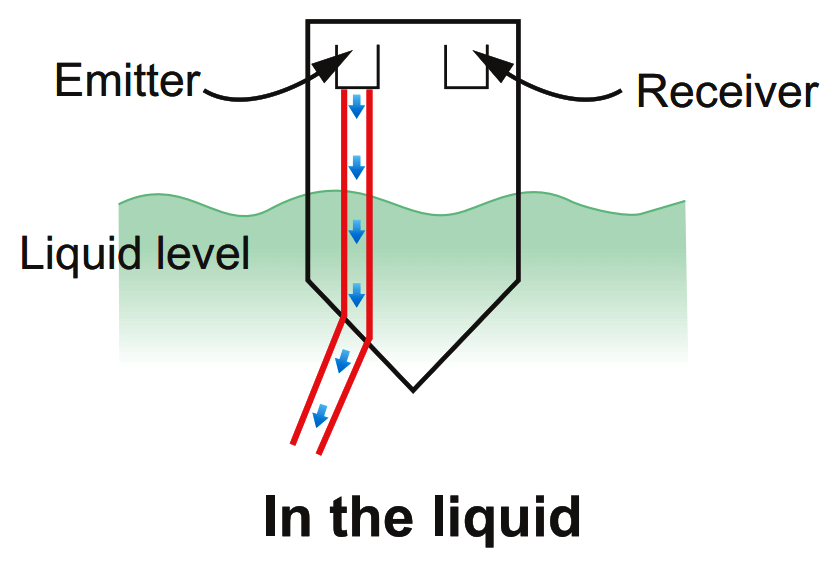
Totally reflected light will be transmitted to the receiver. Conversely, when the sensor is surrounded by liquid, due to the refractive index of the liquid and the sensor tip material, almost all light will penetrate the front of the sensor.

Using this principle, the optical liquid level switch design is based on light. The receiver can detect and determine a light reflected or penetrated state, and determines the circuit output.

Optical Level Switch Principle

Advantages :

  • Simple, compact, and robust
  • No moving parts
  • Built-in, solid-state electronics
  • Easily removed, cleaned, and reinstalled
  • LED switch indication

Article Source : FineTek

Don't Miss Our Updates
Be the first to get exclusive content straight to your email.
We promise not to spam you. You can unsubscribe at any time.
Invalid email address
You've successfully subscribed !

Continue Reading

DP Level Measurement Problems
Purpose of Tank Gauging Level Measurement
What is Dip Tape Level Measurement?
Conductive Level Switch Principle
Proximity switches Circuit Diagram Operation
Safety Switches for Controlling Conveyor Operations
Share This Article
Facebook Whatsapp Whatsapp LinkedIn Copy Link
Share
1 Comment
  • viral patel says:
    December 24, 2019 at 5:15 pm

    please elaborate on optical level switch principle little more

    Reply

Leave a Reply Cancel reply

Your email address will not be published. Required fields are marked *

Stay Connected

128.3kFollowersLike
69.1kFollowersFollow
210kSubscribersSubscribe
38kFollowersFollow

Categories

Explore More

Tank Level Detection Switches
ElectroMechanical Level Measurement Working Principle
Capacitance Level Sensor Principle, Limitations, Installation & Calibration
PLC Example with Switches
Hydrostatic Level Measurement
Effects of Symmetric and Asymmetric Capillary Tube Pressure Measurement
Contact Type Guided Wave Radar Level Transmitter Working Principle
Ultrasonic Level Measurement

Keep Learning

Level Sensors MCQ

Level Sensors MCQ – Industrial Instrumentation

Magnetostrictive Tank Gauging Probe

Magnetostrictive Tank Gauging (MTG)

Displacer Level Transmitter Calibration Procedure

Displacer Level Transmitter Calibration using Water & Process Liquid

Elevated Span and Suppressed Span

DP Level Transmitter Elevation and Suppression Corrections

FMCW radar principle

TDR & FMCW Radar Level Transmitters Principle

Closed-tank-DP-Level-Transmitter-with-cleaning-leg-Calibration

Closed tank DP Level Transmitter with cleaning leg Calibration

DP-Level-Transmitter-Open-tank-calibration

Open Tank DP Level Transmitter Calibration

Radiation based Level Sensor Principle

Radiation based Level Sensor Principle

Learn More

Distillation Tower Displacer Level Instrument

Distillation Tower Displacer Level Instrument Check

Piping Schematic for Two Solenoid Valves Double Acting

Different Types of Control Valve Actuators

PLC datasheet

How to Read the PLC Datasheet? – Important Notes About PLC

Ratio Control Example

Ratio Controller Example

Transmission Control Protocol

Difference Between TCP and UDP

Bracelet Scanner

How to Use Bracelet Scanner? – Ultrasonic Thickness Gauge

Mathematical Models of Physical Systems

Block diagram Algebra Objective Questions

Logic Gates Symbols & Truthtables

Logic Gates Animation

Menu

  • About
  • Privacy Policy
  • Copyright

Quick Links

  • Learn PLC
  • Helping Hand
  • Part Time Job

YouTube Subscribe

Follow US
All rights reserved. Reproduction in whole or in part without written permission is prohibited.
Welcome Back!

Sign in to your account

Username or Email Address
Password

Lost your password?