Inst ToolsInst ToolsInst Tools
  • Courses
  • Automation
    • PLC
    • Control System
    • Safety System
    • Communication
    • Fire & Gas System
  • Instrumentation
    • Design
    • Pressure
    • Temperature
    • Flow
    • Level
    • Vibration
    • Analyzer
    • Control Valve
    • Switch
    • Calibration
    • Erection & Commissioning
  • Interview
    • Instrumentation
    • Electrical
    • Electronics
    • Practical
  • Q&A
    • Instrumentation
    • Control System
    • Electrical
    • Electronics
    • Analog Electronics
    • Digital Electronics
    • Power Electronics
    • Microprocessor
  • Request
Search
  • Books
  • Software
  • Projects
  • Process
  • Tools
  • Basics
  • Formula
  • Power Plant
  • Root Cause Analysis
  • Electrical Basics
  • Animation
  • Standards
  • 4-20 mA Course
  • Siemens PLC Course
Reading: Inductively Coupled Wire Guided Float Detectors
Share
Notification Show More
Font ResizerAa
Inst ToolsInst Tools
Font ResizerAa
  • Courses
  • Design
  • PLC
  • Interview
  • Control System
Search
  • Courses
  • Automation
    • PLC
    • Control System
    • Safety System
    • Communication
    • Fire & Gas System
  • Instrumentation
    • Design
    • Pressure
    • Temperature
    • Flow
    • Level
    • Vibration
    • Analyzer
    • Control Valve
    • Switch
    • Calibration
    • Erection & Commissioning
  • Interview
    • Instrumentation
    • Electrical
    • Electronics
    • Practical
  • Q&A
    • Instrumentation
    • Control System
    • Electrical
    • Electronics
    • Analog Electronics
    • Digital Electronics
    • Power Electronics
    • Microprocessor
  • Request
Follow US
All rights reserved. Reproduction in whole or in part without written permission is prohibited.
Inst Tools > Blog > Level Measurement > Inductively Coupled Wire Guided Float Detectors

Inductively Coupled Wire Guided Float Detectors

Last updated: December 14, 2019 9:54 am
Editorial Staff
Level Measurement
No Comments
Share
3 Min Read
SHARE

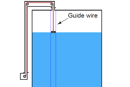
Inductively Coupled Wire Guided Float Detectors is an old method of level measurement used in the fuel storage industry. This system has a wire that is fixed at both the top and bottom of the tank and is used as a guide and a source of power for the float. The float contains an inductively coupled transducer, powered by the guide-wire.

During operation the primary coupling of the transducer is periodically interrupted, allowing a secondary inductive coupling of the transducer between the wire and float transducer. Level Measurement is achieved through conductors placed at known intervals on the guide-wire, which produces a ‘grey’ encoded-word that is then communicated back up to the display unit.

Wire Guided Float Detectors
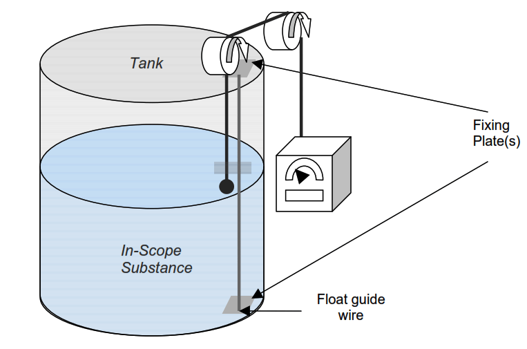
Wire Guided Float Detectors

This type of system should only be used in ‘clean’ measuring applications, therefore it is suitable for gasoline level measurement.

This is a widely used level measurement method, however, its perceived accuracy is not considered good enough for either custody transfer or stock accounting measurement.

Another drawback with inductively coupled wire-guided floats is that they can be prone to ‘tape hang-ups’. This can occur when material builds up on the guide-wire which then hinders the movement of the float. This problem would become worse with viscous material measurement.

Components of inductively coupled wire-guided float systems are prone to accelerated wear because of continuous movement of the drive mechanism that is connected to the float on the liquid surface. Therefore the level of reliability of this method can be potentially poor.

Industry experts have spoken to suggest that this method of tank gauging should no longer be used because of the varying levels of reliability and accuracy of measurement, and the method’s high maintenance demands.

Float systems are becoming less commonplace mainly because the evolution of the other methods has advanced further than this method. Over time, as these systems break down, many fuel storage facilities are choosing to replace this type of system with different technology.

Read Next:

  • Thermal Differential Level Sensors
  • Level Switches for Storage Tanks
  • Capacitance Level Sensor Principle
  • Magnetostrictive Level Sensors
  • Types of Industrial Level Sensors
Don't Miss Our Updates
Be the first to get exclusive content straight to your email.
We promise not to spam you. You can unsubscribe at any time.
Invalid email address
You've successfully subscribed !

Continue Reading

Stilling Wells for Level Measurement
How to Install Ultrasonic Level Transmitters
Ultrasonic Level Switch Working Principle
DP Transmitter Interface Level Measurement Principle, Limitations, Selection, Installation, Design & Calibration
Differential Pressure Transmitters Compensated Leg Systems
Pressure Transmitters Leg Compensation Technique
Share This Article
Facebook Whatsapp Whatsapp LinkedIn Copy Link
Share
Leave a Comment

Leave a Reply Cancel reply

Your email address will not be published. Required fields are marked *

Stay Connected

128.3kFollowersLike
69.1kFollowersFollow
210kSubscribersSubscribe
38kFollowersFollow

Categories

Explore More

Level Calculation with Remote Seals
Guided-wave Radar Level Measurement Animation
Magnetostrictive Tank Gauging (MTG)
RF Capacitance Level Switch Working Principle
Nuclear Interface Level Measurement Principle, Limitations, Installation and Calibration
Capacitive Level Measurement
Vibrating Fork Level Switch Working Animation
Stilling Well in Interface Level Measurement System

Keep Learning

Differential Pressure Transmitter Zero Suppression

Basics of DP Transmitter Suppression and Elevation

Magnetic Float Level Sensor Principle

Magnetic Float Level Transmitter Working Principle

Guide Wire Level Measurement

Float Level Measurement

Closed Tank Level Measurement using DP Transmitter

How can we use a DP Flow Transmitter for Level Measurement

Non‐contact RADAR Level Transmitter Pulse

Non Contact RADAR Level Transmitter Principle, Limitations, Design, Installation and Calibration

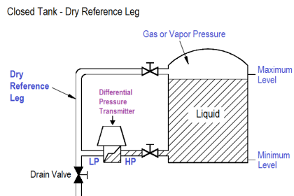
Closed Tank - Dry Reference Leg

Basics of Level Measurement

Level Gauge Working Animation

Sight Glass Level Measurement Principle

Bubble Tube Level measurement

Bubble Tube Level Measurement Principle

Learn More

Digital Electronics Multiple Choice Questions

Triggering of Flip Flops Objective Questions

PLC Programming for Automated Curtain Control

Automatic Curtain Control – PLC Programming Solution

PLC Ladder Program for Automatic Car Wash

PLC Ladder Program for Automatic Car Wash using Siemens TIA Portal

Electrical Frequency

One Nation One Grid One Frequency – Electrical Engineering

failure rate of a component - 1

Failure rate and MTBF of Safety Instrumented Systems

Example of PLC Programming based on Logic Circuit

Example of PLC Programming based on Logic Circuit

Industrial Flame Detectors

Industrial Flame Detectors

tk3 calibration instrument

What is TK-3 Calibrator ?

Menu

  • About
  • Privacy Policy
  • Copyright

Quick Links

  • Learn PLC
  • Helping Hand
  • Part Time Job

YouTube Subscribe

Follow US
All rights reserved. Reproduction in whole or in part without written permission is prohibited.
Welcome Back!

Sign in to your account

Username or Email Address
Password

Lost your password?