Inst ToolsInst ToolsInst Tools
  • Courses
  • Automation
    • PLC
    • Control System
    • Safety System
    • Communication
    • Fire & Gas System
  • Instrumentation
    • Design
    • Pressure
    • Temperature
    • Flow
    • Level
    • Vibration
    • Analyzer
    • Control Valve
    • Switch
    • Calibration
    • Erection & Commissioning
  • Interview
    • Instrumentation
    • Electrical
    • Electronics
    • Practical
  • Q&A
    • Instrumentation
    • Control System
    • Electrical
    • Electronics
    • Analog Electronics
    • Digital Electronics
    • Power Electronics
    • Microprocessor
  • Request
Search
  • Books
  • Software
  • Projects
  • Process
  • Tools
  • Basics
  • Formula
  • Power Plant
  • Root Cause Analysis
  • Electrical Basics
  • Animation
  • Standards
  • 4-20 mA Course
  • Siemens PLC Course
Reading: VFD Commissioning and Testing Procedure (Variable Frequency Drive)
Share
Notification Show More
Font ResizerAa
Inst ToolsInst Tools
Font ResizerAa
  • Courses
  • Design
  • PLC
  • Interview
  • Control System
Search
  • Courses
  • Automation
    • PLC
    • Control System
    • Safety System
    • Communication
    • Fire & Gas System
  • Instrumentation
    • Design
    • Pressure
    • Temperature
    • Flow
    • Level
    • Vibration
    • Analyzer
    • Control Valve
    • Switch
    • Calibration
    • Erection & Commissioning
  • Interview
    • Instrumentation
    • Electrical
    • Electronics
    • Practical
  • Q&A
    • Instrumentation
    • Control System
    • Electrical
    • Electronics
    • Analog Electronics
    • Digital Electronics
    • Power Electronics
    • Microprocessor
  • Request
Follow US
All rights reserved. Reproduction in whole or in part without written permission is prohibited.
Inst Tools > Blog > PLC Tutorials > VFD Commissioning and Testing Procedure (Variable Frequency Drive)

VFD Commissioning and Testing Procedure (Variable Frequency Drive)

In this article, we will learn the commissioning and testing procedure for a VFD (Variable Frequency Drive).

Last updated: October 17, 2023 1:49 pm
Viral Nagda
PLC Tutorials Control Systems Electrical Basics
No Comments
Share
6 Min Read
SHARE

In this article, we will learn the commissioning and testing procedure for a VFD (Variable Frequency Drive).

Contents
Importance of Proper VFD CommissioningStandard Guidelines for VFDVFD Commissioning and Testing

Various first-time engineers of industrial automation face a question on what to do when they are asked to test a VFD and it’s working properly.

Well, it is obvious because every new task requires some set of rules and steps to follow for proper execution. So, the commissioning of a VFD is also a tedious task for a new engineer.

In this post, we will see some general guidelines regarding the commissioning of a VFD. Using these, any new engineer can easily test a VD and it’s working afterward.

VFD Commissioning and Testing Procedure

Importance of Proper VFD Commissioning

Before that, let us have a look at the below reasons for why it is important to properly commission a VFD.

  • To ensure that the motor varies it’s speed accordingly and under proper test conditions.
  • To ensure that both the motor and VFD are properly grounded. Without it, there are high chances of electromagnetic interference in the electrical panel and it can interfere with the performance of the nearby equipment. Also, proper earth ensures safety of the personnel and nearby environment.
  • To ensure that it meets the wiring and safety standards like IEC 60364.
  • To ensure that the cables and wires that have been selected are properly sized, installed and terminated.
  • Also, there must not be any fault in the cables before powering up the VFD; otherwise it will damage the circuitry.

Standard Guidelines for VFD

Before starting the commissioning, it is necessary that we follow some below-given standard guidelines for it.

  • Verify the earth loop impedance and the voltage between ground to neutral. It must be less than 0.5 V.
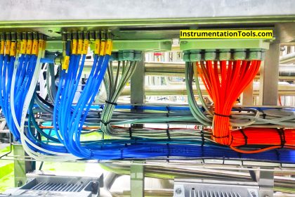
  • Cross check all the connections and cables in the VFD panel and ensure they are properly tightened and installed.
  • Also, check cables dressing, ferruling and ensure that the cable is connected to it’s respective polarity.
  • Verify that whether all the wiring has been done according to electrical drawing or not.
  • Ensure that the VFD is properly fitted in the panel and check for any damage in the VFD. If you observe any damage in the installation parts or VFD itself, get it repaired or replace it. It is not advisable to power up the VFD with any damage in it.
  • In the electrical panel, check whether all the fuses / line chokes / harmonic filters are properly connected or not.
  • Cross check the motor and VFD specifications and see whether only the selected model is installed or not.
  • Ensure that both the motor and VFD are properly grounded.
  • You need to do Megger test to see that all the cables are damage free.
  • VFD is not always used alone. It is used with PLC and other control system for interface. So, if such means is used, check the control wiring from PLC or if communication is used, then check it’s cabling and port connection.
  • As VFD dissipates a large amount of heat, see that proper cooling and ventilation methods are used around it and it’s internal fan is proper or not.
  • If mechanical brakes are used with the motor, check it’s installation and also check the installation of dynamic brake resistor boxes.

VFD Commissioning and Testing

Now that you have verified all the pre-requisite conditions, do the following steps for commissioning:

  • Check the input supply voltage given, before powering up the VFD.
  • After verifying, power ON the VFD. First check the DC voltage at the DC bus voltage output of VFD.
  • As soon as VFD power ups, it’s fan starts working. See whether it’s proper or not.
  • Now, enter the required parameters in the VFD. The generally used ones are – control parameters (source of command and speed reference), IO configuration (inputs and outputs of VFD control terminals, fault management, motor control parameters (current, voltage, rpm, frequency etc.) and acceleration and deceleration times.
  • Give run command and speed reference to the VFD, and check whether the motor is rotating in given direction or not.
  • Ensure that the motor is running in it’s rated specifications and any trip should not occur in the VFD. There should not be any abnormal noise coming from the running motor.
  • If you need to do auto-tuning depending on your application, read the VFD catalogue properly and follow the given steps for tuning it.
  • Power recycle the same procedure and see whether it is functioning in the same way or not.

In this way, we saw how to commission a VFD.

If you liked this article, then please subscribe to our YouTube Channel for Instrumentation, Electrical, PLC, and SCADA video tutorials.

You can also follow us on Facebook and Twitter to receive daily updates.

Read Next:

  • Star Delta Starter
  • DCS Commissioning
  • PLC Commissioning
  • Electrical Wiring Diagram
  • NEMA and IEC Motors
Don't Miss Our Updates
Be the first to get exclusive content straight to your email.
We promise not to spam you. You can unsubscribe at any time.
Invalid email address
You've successfully subscribed !

Continue Reading

PLC Ladder Logic for Tanks Filling as per Priority
Vijeo Designer software – Import and Export
While Do Statement in Structured Text PLC Program
Difference Between Alternator and Generator?
What is a Wave Trap? – Power Line Carrier Communication
PLC Pneumatic Circuit Control
Share This Article
Facebook Whatsapp Whatsapp LinkedIn Copy Link
Share
Leave a Comment

Leave a Reply Cancel reply

Your email address will not be published. Required fields are marked *

Stay Connected

128.3kFollowersLike
69.1kFollowersFollow
210kSubscribersSubscribe
38kFollowersFollow

Categories

Explore More

PLC based 4 Way Traffic Light Control System
How to Protect Electrical Terminal Blocks From Tampering?
How Do Electrical Shorts and Ground Faults Trip Circuit Breakers?
Configuration of Input and Output Tags in Siemens Scada and PLC
PLC Program for Mixing Tank
Difference Between PLC and CNC Machine
Complex Car Parking Logic in XG5000 LS Electric PLC
Allen Bradley PLC Subroutines

Keep Learning

What is FAT and SAT?

What is FAT and SAT? Difference between them

4-20mA Loop Power Supply Questions

4-20mA Loop Power Supply Questions and Answers

Programming in Omron PLC

Automatic Vacuum Cleaner Programming in Omron PLC

Process Automation

What is Process Automation? – Simple Automation Example

Electrical Feeder Automation in Smart Grid

Electrical Feeder Automation in Smart Grid

Ladder Logic Counters Instruction

Up Counter PLC Program

A typical wiring diagram from Field Transmitter to Control Room

How to Wire a Field instrument to Control Room with Example

Readings Mismatch between Field & Control Room

Readings Mismatch between Field & Control Room ? Why

Learn More

How to Locate Faults in Cables? - Fault Analysis and Location

How to Locate Faults in Cables? – Fault Analysis & Location

Omron PLC increment and decrement

Increment & Decrement Instructions in CX-Programmer (OMRON)

Voltage and Current Phase Relationships in an Inductive Circuit

Voltage and Current Phase Relationships in an Inductive Circuit

NH3 Storage Tanks Ammonia Gas

NH3 Storage Tanks Ammonia Gas Venting Issue – Root Cause Analysis

Why are Impulse Lines often Installed in a Sloping Manner (Angle)

Why are Impulse Lines often Installed in a Sloping Manner?

IEC Area Classification System

Ex ic Intrinsic safety Standard

online silica analyzer

Silica Analyzer Problems and Troubleshooting Tips

PLC Program with 2 Toggle Switches and 4 Motors

PLC Program with 2 Toggle Switches and 4 Motors

Menu

  • About
  • Privacy Policy
  • Copyright

Quick Links

  • Learn PLC
  • Helping Hand
  • Part Time Job

YouTube Subscribe

Follow US
All rights reserved. Reproduction in whole or in part without written permission is prohibited.
Welcome Back!

Sign in to your account

Username or Email Address
Password

Lost your password?