Despite senior colleagues’ diffidence & seemingly no solution a last minute hitch, 220-bar syn gas cooler successfully re-tubed.
| Article Type: | Root Cause Analysis (RCA) |
| Category: | Mechanical |
| Equipment Type: | Pipelines and Miscellaneous Problems |
| Author: | S. Raghava Chari |
Note: This root cause analysis (RCA) is from real-time scenarios that happened in industries during the tenure of two or three decades ago. These articles will help you to improve your troubleshooting skills and knowledge.
Problem Details
3 heat exchangers cool the ammonia converter exiting partially converted into NH3 gases. The fourth coolers are shell and U-tube heat exchanger E-704 A and identical parallel E‑704 B.
Tube-circuit fluid is 220 bars 125o C converter effluent gases. Shell circuit fluid is 34o C Cooling Water (CW). The cooled to 45o C gases contained large quantities liquid ammonia collects in a tall vertical vessel called ammonia separator (AS) bottom.
The condensed ammonia letdown to 17-bars major portion goes for urea production and the balance to a refrigeration cycle.
AS exiting gases undergo further cooling to recover more ammonia and the ammonia stripped gases a H2 N2 and small quantities NH3 mixture recycle back to the ammonia convertor with makeup synthesis gas for ammonia production.
70o C outlet gas temp clearly confirmed both exchanger’s inadequate surface areas. The author, instrument engineer roughly estimated 20 to 30% heat transfer area increase necessary.
Then, the operation and tech service engineers studied seriously and suggested increasing both the exchangers’ heat transfer area by 30%.
By then the author promoted as maintenance manager suggested:
- Re-tube the retired nearly same configuration and heat transfer area boiler feed water heater E-702 and tag it as E-704 A
- While re-tubing, fit longer U-tubes to increase the heat transfer area and shell length to suit. Install it as E-704-A during the year later Turnaround.
- The AS will show liquid NH3 collection first time in 10 years i.e. ammonia production will increase by 10%
- Re-tube removed E‑704 A also increasing the heat transfer area and install it in place of E‑704 B
- Thanks to both increased heat transfer area heat exchangers ammonia production would exceed rated capacities
The high pressure, temperature, expanded tube to tube sheet joint seal welds, similar jobs never done before, and perhaps the mechanical engineering graduate author Instrument and Electrical experience only, and oppose any new endeavors skeptics influence intimidated many senior managers.
Hence, highly diffident they discouraged the plant re-tubing and recommended importing two new exchangers. This would cost Rs 49 million more and delay achieving higher than rated capacity ammonia production by 18‑24 months. However, the General Manager disregarding the objections waved the green flag.
The airfreighted longer U-tubes reached in two months. Their insertion, shell extending, exchanger assembly, tube-sheet to tubes expansion and seal welds i.e. the retubing was complete in 45 days – 15 days ahead of schedule.
However, the entire 800 Nos. joints leaked on 1-bar air leak test. Dye Penetrant test showed all seal welds cracked. The crew ground them off and seal welded again. However, leaks persisted. Similar 2nd attempt too failed.
The mercilessly taunted and crest fallen author consulted welding rods suppliers, nearby nuclear power plant metallurgists, and renowned high-tech institutes. None had an answer.
Undaunted, he consulted books on stainless steel welding as the incolloy buttering layer over the chrome-moly tube-sheet belongs to SS family.
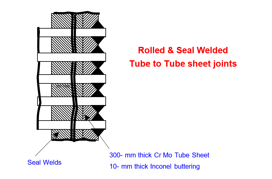
To answer curious readers, the 300o C, 220 bar hydrogen rich convertor effluent gas wetted E-702 requires 300 mm thick Cr-Moly tube sheet.
Even tiny welding e.g. seal welding tubes on even 20 mm thick carbon or alloy steels requires stress relieving but welding on 300 series stainless steels layers do not.
Hence, the factory welded 10‑mm thick incolloy over-lay aka buttered the tube-sheet and stress relieved the entire channel head in their huge furnace.
This way, minor field welds e.g. joints seal welding after re-tubing, or plugging leaky tubes do not require the near impossible site stress relieving.
The author continued his search for an answer. American Oil Co published a small booklet on SS Welding clued the problem that eluded in-house welding stalwarts, atomic power plant and high-tech engineering colleges metallurgists.
The book emphasizes extreme cleanliness while SS welding; particularly carbon contamination prevention. It warns that even pencil marks at the weld area could crack the weld! The SS’s Cr reacts with the carbon, forms brittle chromium carbide, which cracks on cooling.
Obviously, the inevitable oiling – oil is a hydro carbon – while tubes rollers expanding IS THE CARBON CONTAMINATION – the CRACKED and LEAKY Tube Sheet Seal Weld Leaks’ ROOT CAUSE!
Having identified RC from the booklet given clue, the author devised the below given remedy also:
- Grind off all seal welds
- Tri-chloro ethylene wash the oil at the seal welds
- Interconnect the shell ckt to the tube ckt and evacuate using the instrument section vacuum pump
- Simultaneously heat the tube sheet to around 200o C using electric heating elements for say 6 hours
- Hope heating and evacuation would remove oil from the joints and new welds will be leak free. In the meantime, pray vigorously and think what else to do if this fails
It worked! The author cautioned crew first seal welded 20 Nos. lowest tubes, then oil lubed roller expanded and tested. As he advised, the crew cautiously avoided oil contamination of other joints.
These joints passed air leak tests the very first time. The encouraged crew seal welded 20 more next upper layer joints, then lubed roller expanded and tested.
These too passed the very first time. The doubly encouraged crew cautiously moving upwards completed all the joints this way; none leaked.
In addition, the tube circuit passed required 375 bars and the shell 6-bars hydraulic tests also. The re-tubed E‑702 tagged E‑704 A went in position during the turnaround (TA).
Easier and Quicker Method to Clean Oil from the Seal Weld Areas
An Easier and Quicker Method to Clean Oil from the Seal Weld Areas found almost 30-years later follows (fig) :
- Grind off all the seal welds
- Plug the gas inlet and exit nozzles
- Make a 15 mm plate to cover the channel head; bolt it with two original bolts; use a near 6-mm thick used conveyor belt piece as gasket
- Bolt a 500 W electric heater to the cover;
- Wire 220 V power supply via a pressure switch off at 200o C air temp
- Fill 3-bars air in the channel head and U-tubes via an air pressure regulator
11% increased ammonia production delighted one and all including the against the proposal diffident skeptics.
The author revised the removed E-704 A retubing procedure as below:
- Expand 20 Nos. of bottom most tubes to touch the tube sheet bore outer edge by lightly hammering an inserted 50 mm long 5o taper plug
- Seal weld
- Now expand using oiled rollers as usual. Take care to avoid oil contamination of other joints. This is the reason for starting from the bottom most row and moving upwards
- Proceed further if the joints pass dye and air leak tests
The 20-joints passed dye and air leak the first time. The jubilant crew completed the entire retubing incident free after 2nd 20 tubes’ reconfirmation. The exchanger passed hydraulic tests also.
Re-tubed higher heat transfer area
Re-tubed higher heat transfer area E-704A & B Benefits
In-house re-vamped E-704 A&B benefits are:
- Consistent year round 110% rated capacities NH3 production
- That too a year sooner – the German maker delivery time
- Rs. 50 million foreign exchange savings – 80 figures
- Morale boosted maintenance and operating crew’s boosted confidence to handle still tougher tasks still better
Author: S. Raghava Chari
Do you face any similar issues? Share with us through the below comments section.
If you liked this article, then please subscribe to our YouTube Channel for Instrumentation, Electrical, PLC, and SCADA video tutorials.
You can also follow us on Facebook and Twitter to receive daily updates.
Read Next:
- Plug Valves Leaks
- Rupture Discs bursts
- Trip Throttle Valve RCA
- Repeat Safety Valve Popping
- Steam Letdown Station Problems