Inst ToolsInst ToolsInst Tools
  • Courses
  • Automation
    • PLC
    • Control System
    • Safety System
    • Communication
    • Fire & Gas System
  • Instrumentation
    • Design
    • Pressure
    • Temperature
    • Flow
    • Level
    • Vibration
    • Analyzer
    • Control Valve
    • Switch
    • Calibration
    • Erection & Commissioning
  • Interview
    • Instrumentation
    • Electrical
    • Electronics
    • Practical
  • Q&A
    • Instrumentation
    • Control System
    • Electrical
    • Electronics
    • Analog Electronics
    • Digital Electronics
    • Power Electronics
    • Microprocessor
  • Request
Search
  • Books
  • Software
  • Projects
  • Process
  • Tools
  • Basics
  • Formula
  • Power Plant
  • Root Cause Analysis
  • Electrical Basics
  • Animation
  • Standards
  • 4-20 mA Course
  • Siemens PLC Course
Reading: Traffic Light Control using PLC Ladder Logic
Share
Font ResizerAa
Inst ToolsInst Tools
Font ResizerAa
  • Courses
  • Design
  • PLC
  • Interview
  • Control System
Search
  • Courses
  • Automation
    • PLC
    • Control System
    • Safety System
    • Communication
    • Fire & Gas System
  • Instrumentation
    • Design
    • Pressure
    • Temperature
    • Flow
    • Level
    • Vibration
    • Analyzer
    • Control Valve
    • Switch
    • Calibration
    • Erection & Commissioning
  • Interview
    • Instrumentation
    • Electrical
    • Electronics
    • Practical
  • Q&A
    • Instrumentation
    • Control System
    • Electrical
    • Electronics
    • Analog Electronics
    • Digital Electronics
    • Power Electronics
    • Microprocessor
  • Request
Follow US
All rights reserved. Reproduction in whole or in part without written permission is prohibited.
Inst Tools > Blog > PLC Tutorials > Traffic Light Control using PLC Ladder Logic

Traffic Light Control using PLC Ladder Logic

Last updated: March 4, 2021 3:55 pm
Editorial Staff
PLC Tutorials
2 Comments
Share
3 Min Read
SHARE

We most often come across a three-way traffic jam in our city. This PLC program gives the solution to control heavy traffic jams using programmable logic control.

Contents
Traffic Light Control using PLCProblem SolutionList of Inputs and Outputs for Traffic Control SystemPLC Program for 3-way Traffic control SystemPLC Logic Description for 3-way Traffic Control SystemConclusion:

Traffic Light Control using PLC

traffic light plc program

Problem Solution

  1. They are so many ways to write a program for traffic light control ex: sequencer output method but in this normal input, outputs and timers are used.
  2. Timers are used to give time delay for output to turn ON and OFF.
  3. Reset coil is used at the end to run the program continuously.
  4. Comparator blocks are used to reduce the number of timers used.
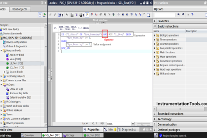
  5. Program done in AB RSLogix 500 Software.

List of Inputs and Outputs for Traffic Control System

simple traffic light plc design

PLC Program for 3-way Traffic control System

Traffic Light Control using PLC Ladder Logic
plc ladder diagram for traffic light control using timers
plc based traffic control system project

Below tabular column gives the Steps or sequence of outputs to turn ON.

traffic light plc programming

PLC Logic Description for 3-way Traffic Control System

RUNG000 :

This is a Latching rung to operate the system through Master Start and Stop PB.

RUNG001 and RUNG0002 :

Starting the timer to turn ON first output West Green so east and west should be in red.

Comparators in Parallel rung are used to turn OFF East red after 15 sec. Timer T4:2 timing bit in parallel contact used to turn ON East red again in 5th  and 6Th  Step. (Refer Above Tabular column for clarification)

RUNG 0003 :

Turning ON North Red up to 3rd step using T4:0 and T4:1’s timer timing bit and comparator blocks.

Rung 0004 :

Turn ON East yellow for 5 sec using comparator blocks. (Step 2nd)

Rung 0005-0006-0007-0008-0009-0010 :

The same procedures followed to turn ON further outputs. ( Refer Tabular column for a sequence of operation)

RUNG 0011 :

Reset coil is turned ON using T4:2 ‘s done bit to restart the cycle from beginning

The program runs continuously until STOP PB is pressed

Conclusion:

The above-explained 3 ways traffic light control using PLC is for example only. It may vary from real-time. We can use this example program to understand the working of timers and comparator block function in AB PLC.

Author: Hema Deepan

If you liked this article, then please subscribe to our YouTube Channel for PLC and SCADA video tutorials.

You can also follow us on Facebook and Twitter to receive daily updates.

Read Next:

PLC Sequential Motor Control

Process Control Loops

PLC Ladder Logic Concepts

What is Loop Checking ?

PLC Test Questions & Answers

Don't Miss Our Updates
Be the first to get exclusive content straight to your email.
We promise not to spam you. You can unsubscribe at any time.
Invalid email address
You've successfully subscribed !

Continue Reading

Difference between PLC and Computers
Siemens Drum block for Sequencer Operation
Statement List (STL) to Find Highest Value
Studio 5000 Tutorial: PLC Programming for Digital Alarms
What is Seal-in Circuit ?
Mitsubishi PLC Timers with Ladder Diagram
Share This Article
Facebook Whatsapp Whatsapp LinkedIn Copy Link
Share
2 Comments
  • Archimedes says:
    March 18, 2019 at 2:55 am

    If it is possible and ok with you, can you get back the pdf downloading for your articles?

    Reply
  • esperant Mputu says:
    February 15, 2023 at 10:32 am

    I loved the explanation and the graphic, it helped me.

    Reply

Leave a Reply Cancel reply

Your email address will not be published. Required fields are marked *

Stay Connected

128.3kFollowersLike
69.1kFollowersFollow
210kSubscribersSubscribe
38kFollowersFollow

Categories

Explore More

Create PLC Program based on Logic Circuit
What is a Relay? Types of Industrial Relays
Connect to the Siemens S7 PLC
PLC Brands Software Information
Two Hand Control Logic using PLC
Timers using Statement List (STL) PLC Programming
PLC Programming Best Practices and Tips
Compare Online and Offline PLC Programs

Keep Learning

Database for each safety module

Global Acknowledgment Instruction in Safety PLC

PLC and MCC Panel Interface Design

PLC Panel and MCC Panel Interface Signals

Industrial Oven Control Application with PLC Controller

Industrial Oven Control Application with PLC Controller

Real-time and historical SCADA Trends

What are Trends in SCADA?

Example Ladder Logic Diagram

What is Relay Logic ?

100 PLC Quiz Questions

100 PLC Quiz Questions : True or False

Difference Between Microcontroller and PLC

Difference Between Microcontroller and PLC

Track PLC Operating Modes

#2 PLC Best Practices – Track Operating Modes

Learn More

Electrical Wiring Terminology

Electrical Wiring Terminology

Three-valve Manifold on Remote Seal DP Transmitter

Three-valve Manifold on Remote Seal DP Transmitter

Purpose of Float Valve

What is a Float Control Valve? Types, Advantages, Disadvantages

Weir Diaphragm Valve

Diaphragm Valves Construction, Types, Stem & Bonnet Assembly

PLC program Permissive Circuit

PLC Electric Motor Interlocks

Difference between Stepper Motor and DC Motor

Difference between Stepper Motor and DC Motor

How to Remove Control Valve Stem Packing Procedure

The Replacement Procedure for Control Valve Stem Packing

Transformer Efficiency

Transformer Efficiency

Menu

  • About
  • Privacy Policy
  • Copyright

Quick Links

  • Learn PLC
  • Helping Hand
  • Part Time Job

YouTube Subscribe

Follow US
All rights reserved. Reproduction in whole or in part without written permission is prohibited.
Welcome Back!

Sign in to your account

Username or Email Address
Password

Lost your password?