Process Control Systems Philosophy is a cloud environment that is the basis of all I&C-Team Documentations and Activities (Including Systems Architecture), and the main design configurations in such environment will specify the required systems (and relevant Instrumentations) and their requirements/ specifications in Process Plant Project.
In this article, we try to review the interrelations between the Systems Architecture Document (Control & Safety Systems Block Diagram) with Process Control Systems Philosophy.
Process Control Systems Philosophy
At the beginning of detail design engineering of Process Plant Project, I&C-Team shall get the project inputs (requirements and conditions) and by exact investigations shall try to provide suitable Process Control Systems Philosophy of the project (see Figure-1).
As explained in the reference article, I&C-Team shall review and consider different sides of project requirements and conditions to provide the best Process Control Systems Philosophy with the below definition:
“A collection set of documentary or non-apparent Outlooks/ Observations/ Attitudes, Tactics/ Policies, and Plans/ Prognosticates that specifies different parts/ blocks of control & safety systems and instrumentations existed in process plant and clarifies the reasons for selecting each items (/systems) and relevant signal interfacings further to logics and philosophies for Functional/ Operational Facilities.”
By above definition, we can conclude that Process Control Systems Philosophy can help for defining duties and scope of works of each block (/ system) & its elements or components and identifies the specifications and requirements on supplying those items and their relevant functions. On the other hand by using Process Control Systems Philosophy I&C-Team will specify the all required systems and their functionalities and accordingly they reflect the interfacings of such systems in Control Systems Block Diagram (Systems Architecture) document accordingly.
Control Philosophy by Systems View
Let us use Figure-2 to represent different possible systems that may be studied in Process Control Systems Philosophy as basis components for defining and arranging the project-required systems and their interfacings.
First, we review the possible types of such systems and then we try to have an overview of the block diagram showing their functionalities and interfaces. Each process plant project may have one or multiple systems, as mentioned in Figure-2.
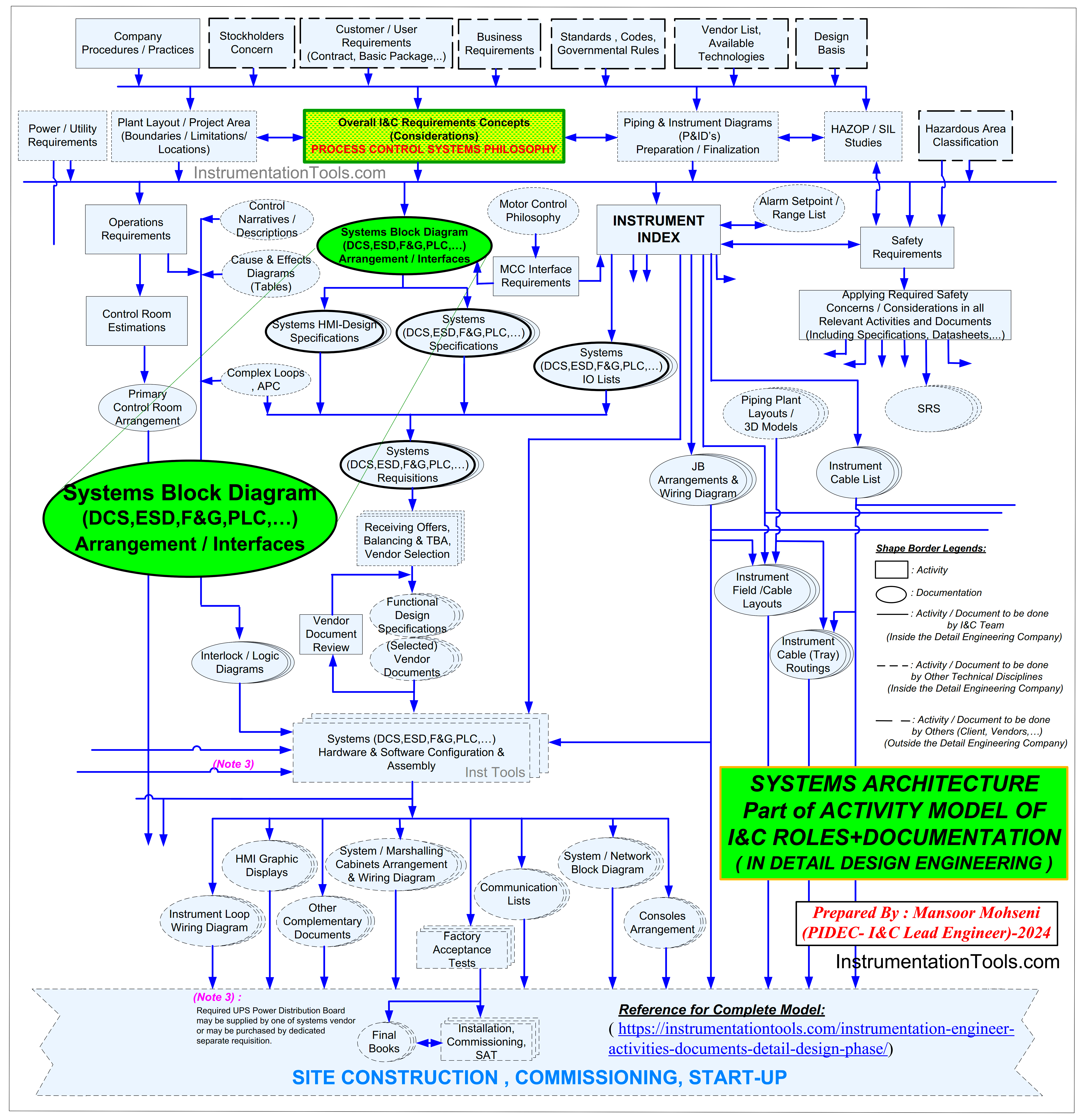
Figure-1: Process Control Systems Philosophy as Basis of all I&C Documents and Activities (Including Systems Architecture)
1. Basic Process Control System (BPCS)
Basic Process Control System (BPCS) is the main required system for a Process Plant Project. Due to the type and size of the project, the Process Plant may include one or multiple BPCS for implementing different control loops of the process.
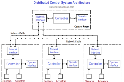
Now for many years, BPCS has been selected as a Distributed Control System (DCS), or after growing digital technologies it can be defined as Digital Control System (DCS). DCS usually is considered as the core system for providing networks and transferring and monitoring Process Plant data.
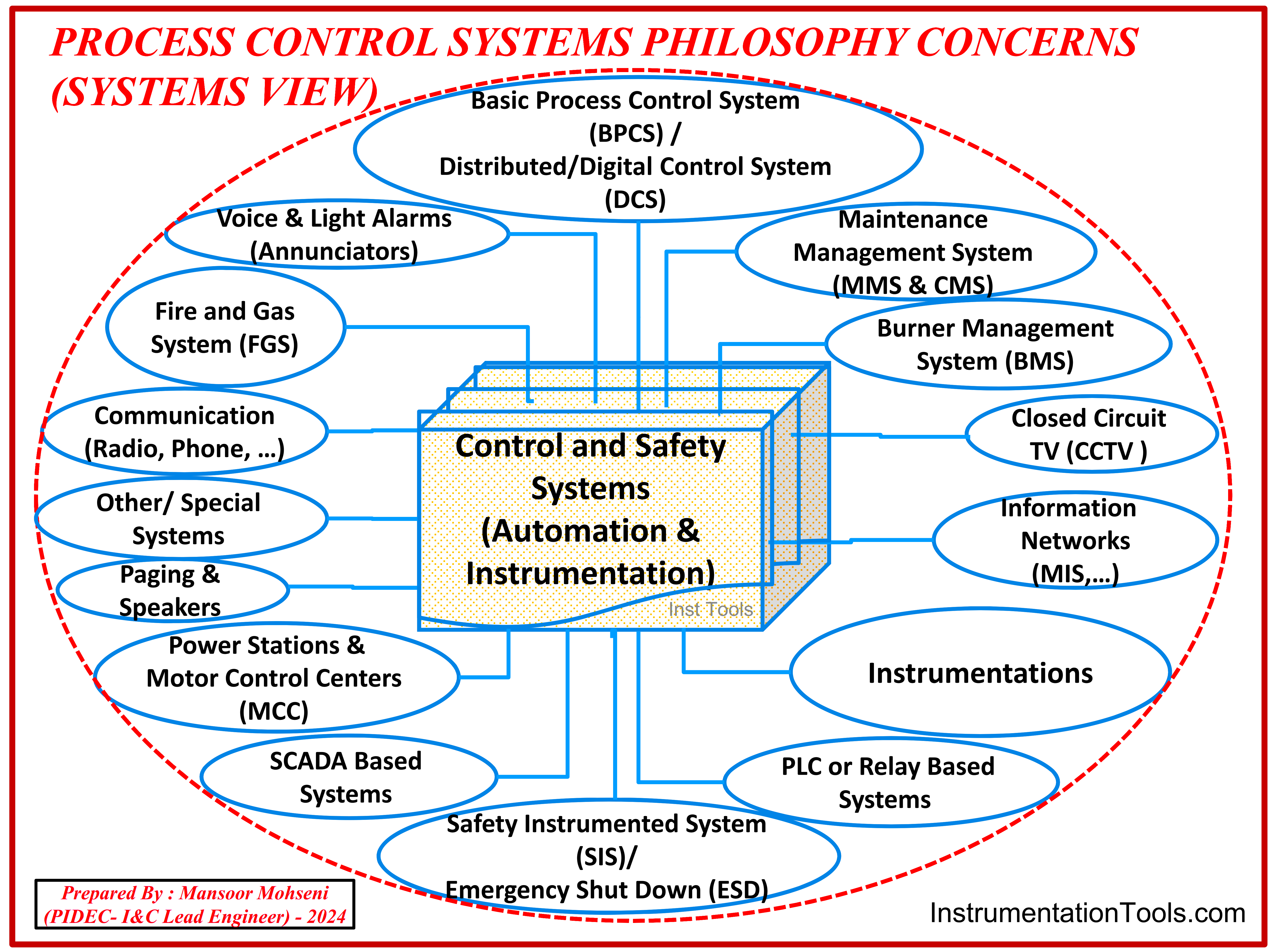
Figure-2: Process Control Systems Philosophy Concerns (Systems View).
2. Safety Instrumented System (SIS)
Safety Instrumented System is a (more) reliable system that protects the plant due to process parameters upsets or any bad or critical conditions. The expected functionality for such a system is to stop (or prevent) suddenly bad states of the process.
By such expectations, usually, such system may be called as Emergency Shut-Down (ESD) System too. Although the reliability of such a system is usually high, but due to the results of SIL (Safety Integrity Level) study meetings, the I&C-Team may investigate for provision of some conditions and requirements to increase the reliability of such a system (and its relevant safety loops).
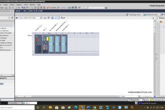
3. PLC or Relay Based Systems
Packages which are used in Process Plants may have their own control and safety systems which are usually implemented by PLC (Programmable Logic Controller) or Relay Based Systems.
However, for some packages required control and safety facilities may be implemented inside Process Plant DCS and ESD Systems. Specifying and implementing the required control and safety systems for different packages of Process Plants is one of the important results of finalizing the Process Control Systems Philosophy.
Some packages of Process Plant may have special dedicated (Electronic/ Digital) controllers which may be considered as Special Systems in our current study. Here it shall be mentioned that in some projects other than Process Plants (usually for Factory Automation Projects), the PLC is the core system (BPCS) for Process Control Systems Philosophy.
4. Instrumentation
For implementing all functionalities of the Process Plant, the Instrumentation & Control (I&C) Team shall design, prepare, or follow all required Instrumentations for all systems inside the Process Control Systems Philosophy. For providing exact data and requirements of Instruments, the I&C-Team shall coordinate exactly with other technical disciplines (especially with PROCESS-Team) for process plant P&IDs and packages that are included inside the project.
The most essential need for Instruments inside the Process Plant which is followed by the I&C-Team, is providing suitable data for Instrumentations like
- The quantity of signals (and instruments) and relevant types,
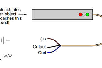
- Their Output or Input Signals,
- The required level of Ingress Protection,
- Their required Hazardous Area Protection Classification Code,
- Their wirings and terminations,
- Power Requirements and other utility consumptions (like Instrument Air),
- Their Operating voltages (and currents),
- They required auxiliary items, Hook-ups, and so on.
It is very important that I&C-Team tries to do the required actions (and documentation) for making harmonized and synchronous (uniform) instrumentations inside the process plant (which are followed by I&C-Team) and the instruments included inside packages (which are provided by packages vendor’s).
Some package vendors may have some problems for following uniformity Requirements with Process Plant Instrumentations Specifications, in which cases I&C-Team shall try to minimize such deviations and consider suitable matchings with other systems in Process Control Systems Philosophy.
5. SCADA Based Systems
In some Process Plant due to long distances between different systems and instrumentations (or due to other possible reasons), I&C-Team shall follow for providing the specifications (/requirements) for Supervisory Control And Data Acquisition (SCADA) Systems. Due to the type of project in some of the Process plants, the core system is the SCADA system.
6. Power Stations & Motor Control Centers (MCC)
For supplying electric power to all systems inside the Process Control Systems Philosophy, the I&C-Team shall coordinate with the Electrical (EL)-Team to consider suitable power feeders.
However, for controlling all electrical equipment of the Process Plant (electrical actuators like motors) I&C-Team shall coordinate with the Electrical (EL)-Team to consider suitable signal interfacings with MCC.
Details of required activities and coordination for the mentioned items and other possible interactions (like Power Distribution Control Systems = PDCS) can be studied in separate articles (Refer to Instrumentationtools.com).
7. Maintenance Management System (MMS & CMS)
I&C-Team shall investigate (with the help of other technical disciplines) for inclusion of some systems for providing Maintenance Management or Computerized Maintenance Systems (MMS & CMS) facilities.
Such systems mainly include Package/ Equipment Protection Systems like Machine Monitoring Systems (MMS) and Conditional Monitoring Systems (CMS) which basically include the required instrumentation for measuring the vibrations and temperatures of packages (Rotary Equipment) like Motors, Pumps, Compressors, Turbines, and so on (for monitoring or applying protection interlocks).
Of course, the I&C-Team shall provide or follow suitable specifications/ requirements in accordance with Process Plant systems on matching the signals and provision of axillary items (like power supply, panels, wirings, Hazardous Area Protection Classification Code, IP, …).
8. Fire and Gas System (FGS)
The most critical hazards in most of the Process Plant Projects are Fire and Gases (Explosive, Flammable, and Toxic), and for Monitoring and Controlling these risks usually such plants are equipped with Fire & Gas Systems.
Such systems shall detect the relevant hazards, and making suitable alarms for any human or system to do required manual or automatic actions. Similar to other systems, the I&C-Team shall engage in providing specifications/ requirements for relevant signals and instrumentations too.
However, the I&C-Team shall have enough care on project requirements for supplying such systems as dedicated (separate) systems or as part of the Process Plant Safety System and the result shall be reflected in the Process Control Systems Philosophy.
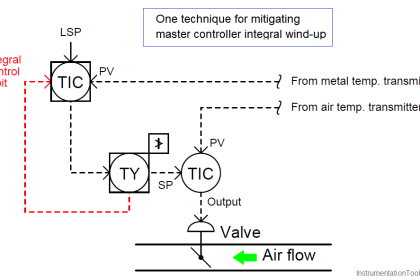
9. Burner Management System (BMS)
Some Process Plants have parts, blocks or packages which are equipped with burners (like furnaces or boilers) and such items are under control and monitoring by special safety systems as Burner Management Systems (BMS).
Since burners working directly with fires (which is the high risk to process plant) special codes and rules shall be considered for these systems, and hence such systems will have interactions with other plant control and safety systems, so I&C-Team shall consider two concerns such as special codes and rules further to satisfying uniformity on matching signals inside Process Control Systems Philosophy, and providing relevant documents (Figure-3).
Now a days, for optimizing the fuel or gas consumptions (and controlling the exact ration of fuel/ gas to air) in burners and reaching the best efficiency for energy savings, Advanced Process Control (APC) systems will have some signal interfacing with burner Management Systems and hence the I&C-Team shall care for such signal matchings too. Furthermore it may require to adding additional facilities/ instruments for implementing excess monitoring and controlling actions.
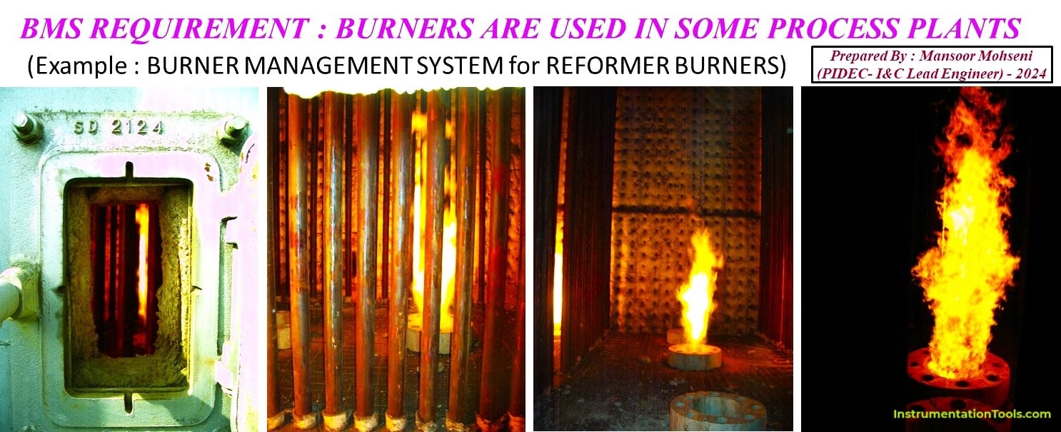
Figure-3: BMS Requirement due to Burners are used in some Process Plants.
10. Voice & Light Alarms (Annunciators)
In order to make quick awareness to site personnel due to occurrence of bad conditions or critical risks, usually some voice and light alarms (annunciators) are located in different places.
Such annunciators may have signal interfacings with safety systems (ESD or FGS) and shall follow standard routines for making suitable (color) light or voices. Each Process Plant may equipped with at least one big Siren/ Horn for whole plant announcing too, which is considered in this part.
11. Information Networks
Further to low level control networks in all Process Plants, some projects may have (higher) networks for transferring data to management levels like Management Information System (MIS) or Asset Management System (AMS) and so on, which I&C-Team shall consider suitable links for transferring data to such networks.
12. Communication (Radio, Phone)
I&C-Team shall know the considered communication media for the plants to consider the required spaces for such systems in control room and using such facilities for implementation of operator activities during operation and maintenance phase (further to start-up and commissioning) of the Process Plant.
13. Closed Circuit TV (CCTV)
The I&C team should be aware of the required facilities for the Paging and Speaker systems and ensure that suitable locations are allocated in the Control Room for the relevant amplifiers.
14. Paging & Speakers
I&C-Team shall know the considered facilities for Paging & Speakers systems, may be to consider suitable places in Control Room for relevant Amplifiers (and also use such facility on special cases for operator helps).
15. Other / Special Systems
Further to above mentioned systems (and items), each Process Plant may have some other / special systems, that I&C-Team shall know about them and their effects on Process Control Systems Philosophy. As an example, as already mentioned in this article some packages may have special Electronic/ Digital systems which is considered in this clause.
However for some systems (that some of them are counted above), the I&C-Team may be not direct responsible for them but shall know their facilities and their effects on Process Control Systems Philosophy (to reflect required interfaces or other requirements in relevant documents).
Process Control Philosophy by Document View
The main concerns of developing Process Control Systems Philosophy during Detail Design (Engineering) and Procurement phases of project execution are providing suitable complete documents that are used to purchase, install, Commission, and Start-up, and Operate and Maintain all required Instrumentation and Systems (even in Operation & Maintenance phase of) Process Plant Project.
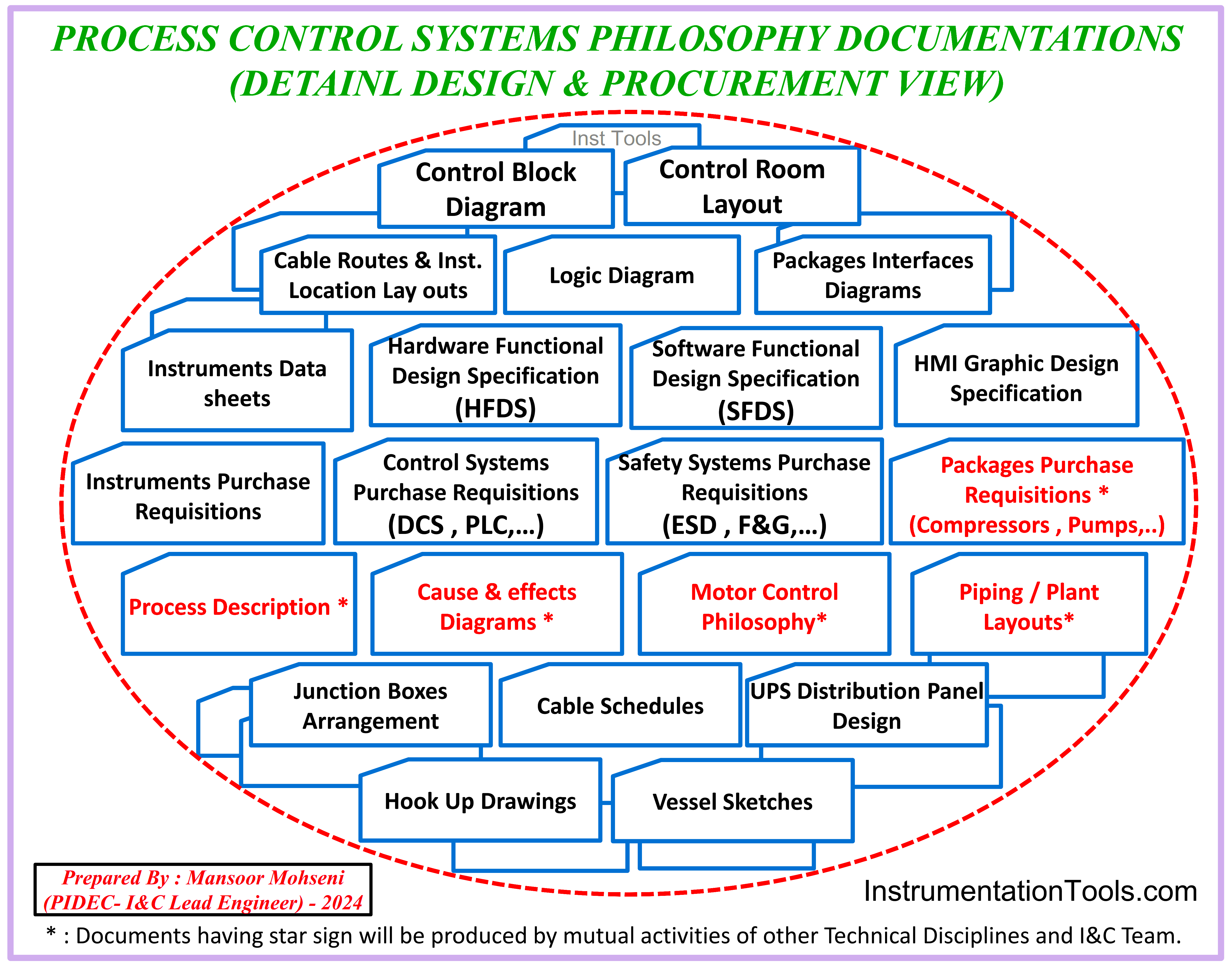
Figure-4: Process Control Systems Philosophy Concerns (Documents View).
Providing any required documents based on Process Control Systems Philosophy may have great effects on Integrity of I&C-Documents. Figure-4 shows the overview of required documentations by considering Process Control systems Philosophy (and detail of such documentations can be found in other articles at Instrumentationtools.com).
As Figure-4 shows such integrated documents may not be completely produced by I&C-Team, but instead they may help other technical disciplines (as mutual interaction activities) for provision of their documents (Items shown by star marks). Also the integrity of I&C-Team documents should be found in documents which are provided by others like vendors too.
Process Control Systems Philosophy From Systems Functional View
I&C-Team shall know the exact functionalities expected from different systems that may be considered inside Process Control Systems Philosophy to satisfy project requirements and accordingly specify required systems for Process Plant Project.
Figure-5 shows general view of Industrial Control Systems (Control Philosophy Blocks + Data Flow) Diagram example for a usual normal Process Plant Project.
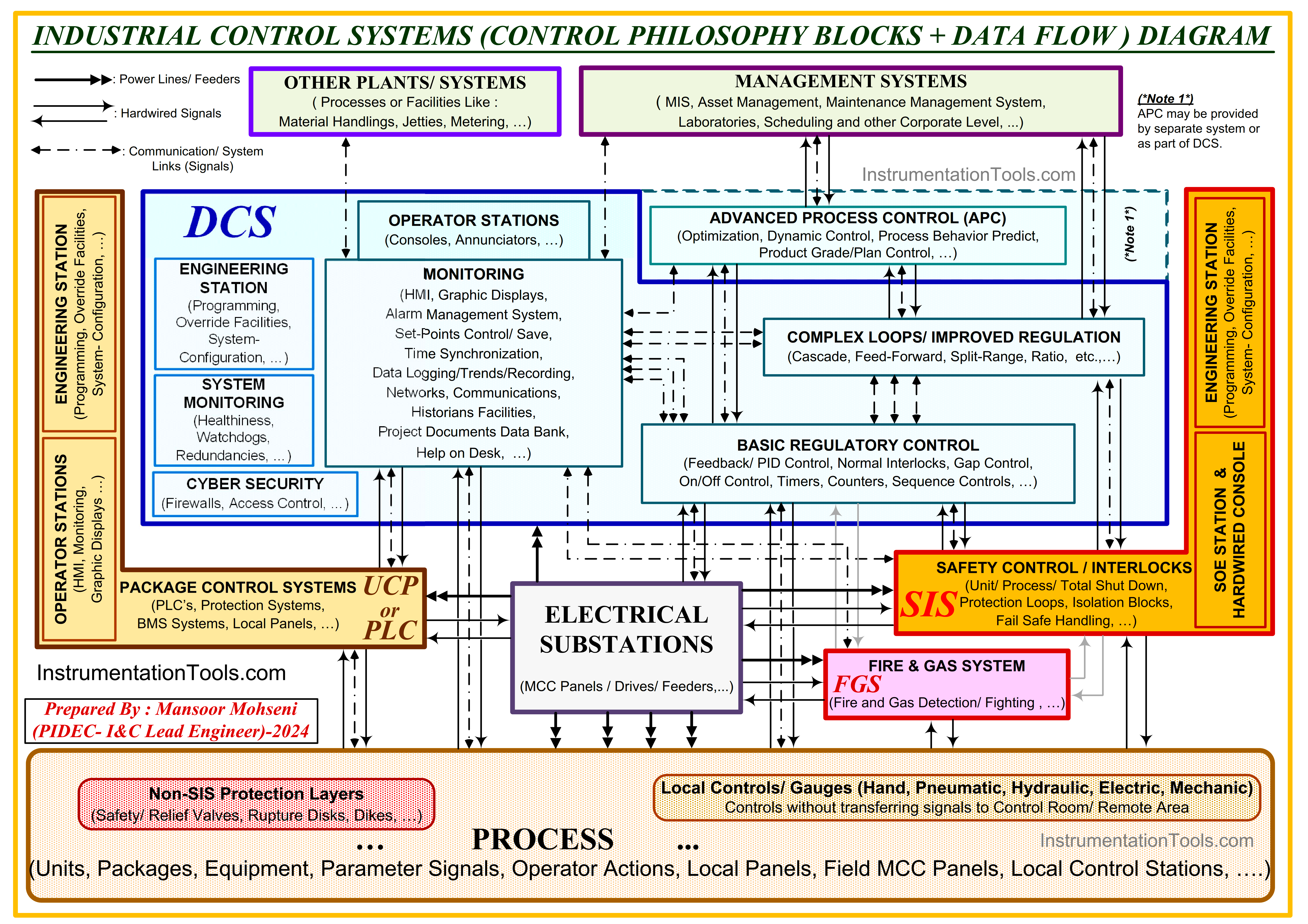
Figure-5: Industrial Control Systems (Control Philosophy Blocks + Data Flow) Diagram for a usual normal Process Plant Project.
It shall be noticed that, Figure-5 is provided as simple model to represent most of all required functionalities of normal Process Plant by simple blocks and selected known words (while in real model of Process Control Systems view of real Process Plant we may found some more details or more dedicated parts or even functionalities), but based on this figure we can define simply different blocks functions as:
Process Site/ Field
The Process Block is the main area of Process Plant of the Project (may called Field or Site) which includes all process items like:
- Units,
- Packages,
- Equipment,
- Parameter Signals,
- Operator Actions,
- Local Panels,
- Field MCC Panels,
- Local Control Stations, and so on.
However Process Site may include some Field/ Local Control level such as:
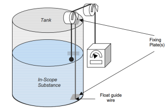
Controls without transferring signals to Control Room/ Remote Area such as Local Controls/ Gauges (Hand, Pneumatic, Hydraulic, Electric, Mechanic).
Also Process Site may include all Non-SIS Protection Layers (without Signal Transfer) like Safety/ Relief Valves, Rupture Disks, Dikes, and so on.
By above explanations, it is clear that the Process Site block is viewed from signal (data) transfer view, and in this regard it is the sources and destinations of most project signals.
Distributed/ Digital Control System (DCS)
Distributed/ Digital Control System (DCS) is the main system for controlling the processes inside project site. The size of required DCS and relevant Hardware (IO’s and other items) and required Software (functionalities) are completely depends on project (Process Site) type and size. The expected functionalities for this system are:
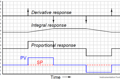
Basic Regulatory Control
Such as Feedback/ PID Control, Normal Interlocks, Gap control, On/ Off Control, Timers, Counters, Sequence Control, etc.
Complex Loops/ Improved Regulation
Such as Cascade, Feed-Forward, Split Range, Ratio, Complex Calculation Blocks, etc.
Monitoring Facilities
Such as HMI, Graphic Displays, Alarm Management System, Set-points Control/ Save, Time Synchronization, Data Logging/ Trends/ Recording, Networks, Communications, Historian Facilities, Project Documents Data Bank, Help on Desk, etc.
Operator Stations
Which are usually appeared as Consoles (Computer Workstations / Monitors) and Annunciators.
Engineering Station
A computer workstation for doing: Programming, Override Facilities, System Configuration, etc.
System Monitoring
Making supervisory on DCS system parts and producing signals/ alarms (such as Healthiness, Watchdogs), and making compensating actions such as redundancies activation.
Cyber Security
Such as firewalls and access controls, etc.
Communication Links and Interfaces
Providing suitable communications and network links further to hardware interfacings (internal and external).
Advanced Process Control (APC)
APC may be provided as extra system connected to DCS or it may be part of DCS for Optimization, Dynamic Control, Process Behavior Predict, Product Grade/ Plan Control, etc.
Safety Instrumented Systems
This system is used for implementing Safety Control Loops/ Interlocks to protect processes from bad conditions or upset values. It includes hardware and software for actions like Protection Loops, Unit/ Process/ Total Shut-Down, Isolation Blocks, Fail Safe handlings, and so on. Further to mentioned facilities and interfaces and communications to other systems, it includes also:
Sequence Of Event (SOE) Recording Station and Hardwired Console.
Fire & Gas System (FGS)
This system is used for detection of Fire and Hazardous Gases (Toxic, Flammable, and Explosive) and producing proper alarms for any further actions (manual or automatic).
Package Control System (UCP or PLC)
This system is used for implementing Safety and Control Loops/ Interlocks for packages, and it may appeared as Unit Control Panel (UCP) or PLC Panel that usually may include PLC’s, Protection Systems (vibration, over-speed , etc.), Burner Management System (BMS), Local Panels, etc.
Furthermore it usually has two other parts:
Operator Stations
Which are usually appeared as Consoles (Computer Workstations / Monitors) and Annunciators. In some cases the operator stations may be consider as panel-mount HMI or console.
Engineering Station
A computer workstation or laptop for doing: Programming, Override Facilities, System Configuration, etc.
Electrical Substations (MCC)
The Power Stations which include MCC Panels, Drives, and Electrical Feeders for driving all consumers (Panels or Field Actuators like Motors, Heaters …).
Further to Power Feeders, such Power Stations will have signal interfacings with different systems too.
Management Systems
This block includes all systems or facilities for supporting Process Control Systems and it may include Management Information System (MIS), Asset Management System, Maintenance Management System, Laboratories, Scheduling and other Corporate Level, etc.
Other Plants/ Systems Interfacings
This block includes all extra systems or plants which will have effects or interfaces with Project Process Control Systems. As example Processes or Facilities Like: Material Handlings, Jetties, Metering Stations, etc.
Possible Links/Communications and Connections
The possible Links/ Communications and Connections between different shown blocks shall be specified schematically.
References:
- Process Control Systems Philosophy Concept
- Interactions With Process Control Systems Philosophy
- 30 concerns for process control systems philosophy
- Instrumentation Design Engineer Roles & Responsibilities