Inst ToolsInst ToolsInst Tools
  • Courses
  • Automation
    • PLC
    • Control System
    • Safety System
    • Communication
    • Fire & Gas System
  • Instrumentation
    • Design
    • Pressure
    • Temperature
    • Flow
    • Level
    • Vibration
    • Analyzer
    • Control Valve
    • Switch
    • Calibration
    • Erection & Commissioning
  • Interview
    • Instrumentation
    • Electrical
    • Electronics
    • Practical
  • Q&A
    • Instrumentation
    • Control System
    • Electrical
    • Electronics
    • Analog Electronics
    • Digital Electronics
    • Power Electronics
    • Microprocessor
  • Request
Search
  • Books
  • Software
  • Projects
  • Process
  • Tools
  • Basics
  • Formula
  • Power Plant
  • Root Cause Analysis
  • Electrical Basics
  • Animation
  • Standards
  • 4-20 mA Course
  • Siemens PLC Course
Reading: How to Use Symbol Factory Software for Graphic Design in HMI or SCADA?
Share
Font ResizerAa
Inst ToolsInst Tools
Font ResizerAa
  • Courses
  • Design
  • PLC
  • Interview
  • Control System
Search
  • Courses
  • Automation
    • PLC
    • Control System
    • Safety System
    • Communication
    • Fire & Gas System
  • Instrumentation
    • Design
    • Pressure
    • Temperature
    • Flow
    • Level
    • Vibration
    • Analyzer
    • Control Valve
    • Switch
    • Calibration
    • Erection & Commissioning
  • Interview
    • Instrumentation
    • Electrical
    • Electronics
    • Practical
  • Q&A
    • Instrumentation
    • Control System
    • Electrical
    • Electronics
    • Analog Electronics
    • Digital Electronics
    • Power Electronics
    • Microprocessor
  • Request
Follow US
All rights reserved. Reproduction in whole or in part without written permission is prohibited.
Inst Tools > Blog > PLC Tutorials > How to Use Symbol Factory Software for Graphic Design in HMI or SCADA?

How to Use Symbol Factory Software for Graphic Design in HMI or SCADA?

In this article, we will learn how to use symbol factory software for graphic design in HMI or SCADA PLC projects.

Last updated: September 14, 2023 1:30 pm
Viral Nagda
PLC Tutorials
1 Comment
Share
5 Min Read
SHARE

SCADA or HMI screen designing is a very competitive thing in industrial automation. The screens and graphics are becoming so demanding nowadays that every colour and design matters.

Contents
Symbol FactoryCreating SymbolsImporting the Image in Paint

Symbol Factory

When operators see something new, they just demand to implement it accordingly if it makes their process simple to use. Due to all these, programmers need to frequently update their design skills for upgradation.

SCADA Tutorial 10 - Symbol Factory in SCADA Software

Apart from standard design libraries available in SCADA / HMI software, many third-party software are available to make the design more aesthetic and beautiful. One of the most used ones is the symbol factory.

In this post, we will see how to use Symbol Factory software for graphic designing.

Creating Symbols

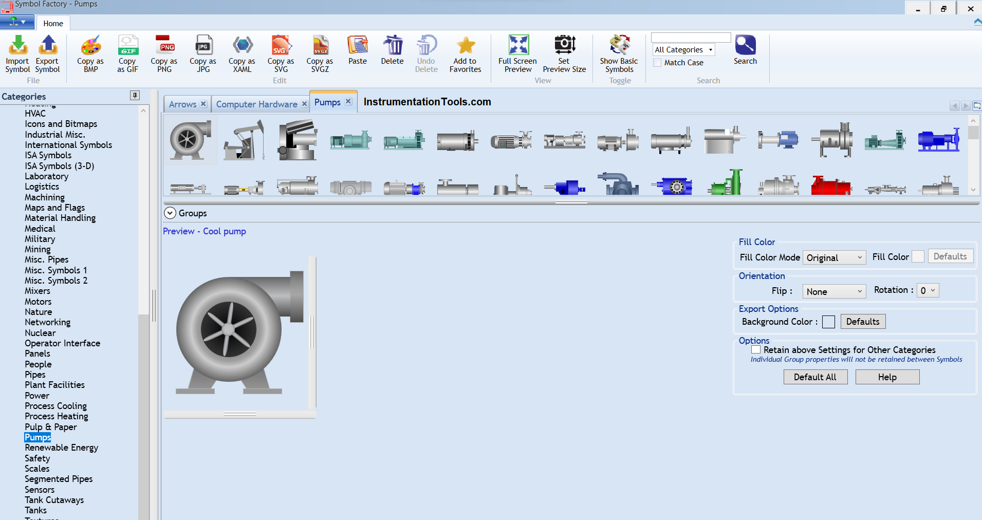
Refer to the below image. The software looks like this. Here, you have many categories when you see it. Each category has various symbols in it, which are pre-defined. These symbols are general and mostly used everywhere in industrial automation.

Let us consider this pump for example as shown.

How to Use Symbol Factory Software for Graphic Design in HMI or SCADA

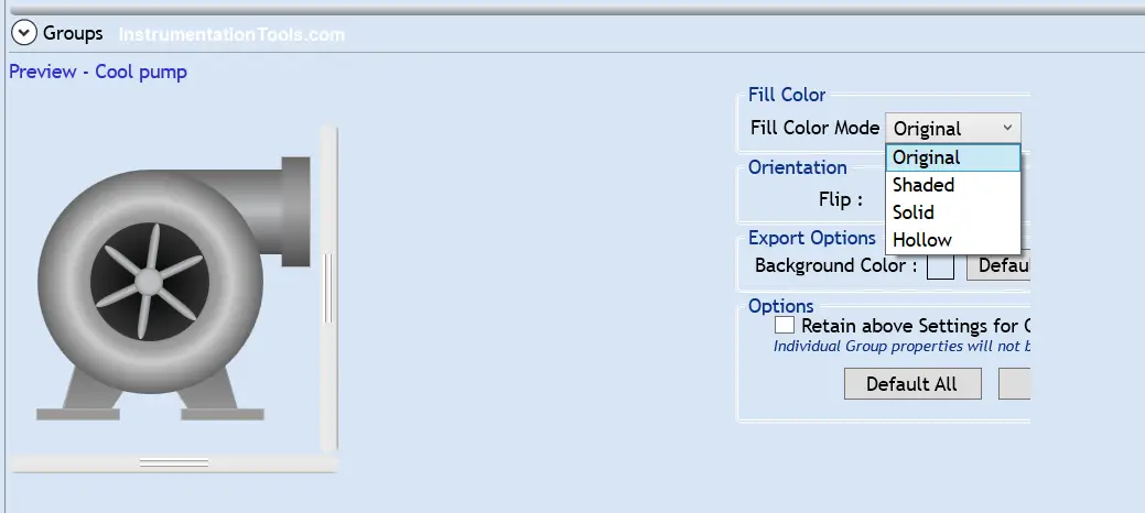
The symbol shown here is a cool pump. In fill colour mode, there are four options – original, shaded, solid and hollow.

The first image shown here is original. It does not give any option for changing its colour. You can only change it’s background colour.

Create new symbol with Symbol Factory

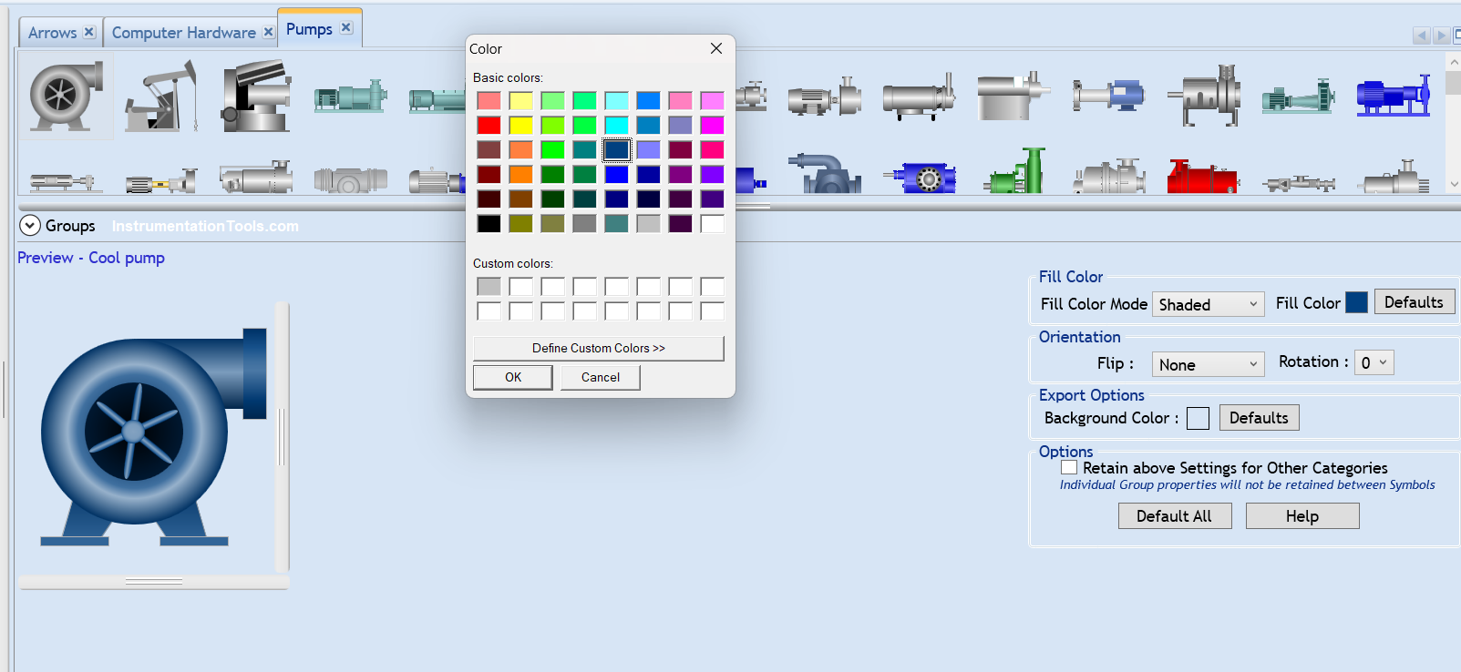
The second image shown below is a shaded one. Here, you change the image colour in shaded format by clicking the fill colour.

This gives an option to insert the image in your graphics in a shaded style. You can only change it’s background colour.

Design the SCADA HMI Symbol Factory

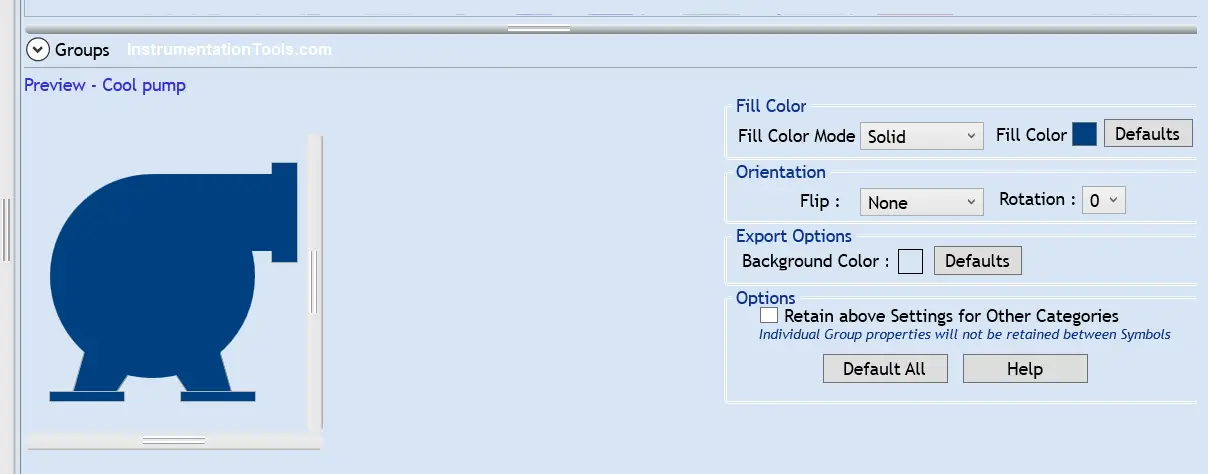
The third image shown below is a solid one. Here, you change the image colour in solid format by clicking the fill colour.

This gives an option to insert the image in your graphics in a solid style. You can only change it’s background colour.

SCADA graphics library download

The fourth image shown below is a hollow one. It does not give any option for changing its colour. You can only change it’s background colour.

As the name implies, you can only see the line background and no colour. So, it is a type of transparent image.

PLC HMI-SCADA Graphics Visualization

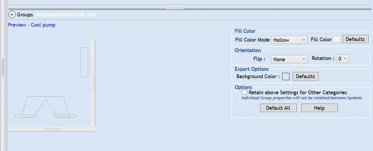
In all these four types, you can flip or rotate the image as required.

Importing the Image in Paint

Once you have created the symbol, you now need to copy it into your graphics software. However, all the software does not have have direct option to paste the image in it.

So, the most simple way is to use paint software. Paint is a universal software which is accepted by all the SCADA / HMI software manufacturers.

PLC Real-Time Graphics for HMI, SCADA

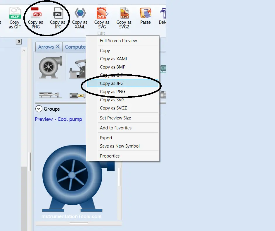
Now, refer to the above image. You need to copy the image as PNG or JPEG, which are the most used ones. Then, open the paint software and just paste it directly. Once you have pasted it, you can then save the image and use it directly in your graphics software.

These are just the general and common steps used to create an image. The software has additional features in it too, it is not possible to discuss everything here. You can install the software and see it for yourself. In this way, we saw how to use symbol factory software for HMI and SCADA development.

If you liked this article, then please subscribe to our YouTube Channel for Instrumentation, Electrical, PLC, and SCADA video tutorials.

You can also follow us on Facebook and Twitter to receive daily updates.

Read Next:

  • Connect Faceplate to PLC Project
  • Instrument Numbering Philosophy
  • How to Fill up Instrument Datasheet?
  • Tagging Philosophy for Junction Box
  • Siemens HMI Training using Faceplates
Don't Miss Our Updates
Be the first to get exclusive content straight to your email.
We promise not to spam you. You can unsubscribe at any time.
Invalid email address
You've successfully subscribed !

Continue Reading

PLC Program for Automatic Liquid Mixing Application
Connect to the Siemens S7 PLC
CX Programmer Example: Perfume Mixing and Filling System
Configuration of Siemens VFD Using TIA Portal Start drive
Modbus Communication between Delta PLC with VFD
Working Principle of Single Phase Preventer Relay
Share This Article
Facebook Whatsapp Whatsapp LinkedIn Copy Link
Share
1 Comment
  • Sunday Adegunna says:
    September 25, 2023 at 8:29 am

    I really like this question and answer and it will help me so much.
    I will like more tutorial on industrial automation and scada PLC.
    Thanks for this information and I look for to hearing from you.

    Reply

Leave a Reply Cancel reply

Your email address will not be published. Required fields are marked *

Stay Connected

128.3kFollowersLike
69.1kFollowersFollow
210kSubscribersSubscribe
38kFollowersFollow

Categories

Explore More

Wiring Diagrams of PLC and DCS Systems – DI, DO, AI, AO
Open User Communication in Siemens Tia Portal – PLC to PLC
Quiz: Identifying I/O Examples in PLC Systems
Auto Sugar Bag Filling Station
PLC Program for Sequential Motor Control
System and Local Time in PLC
PLC Latching Function
How to Convert an Electrical Diagram into PLC Program?

Keep Learning

PLC Programming Example on Timers Function Block

PLC Programming Example on Timers Function Block

PLC Program for Water filling and Discharging Process

PLC Program for Water filling and Discharging Process

Masked Move Instructions

How to use Masked Move Instruction in PLC

Example of Controlling the PLC Output using Push Buttons

Example of Controlling the PLC Output using Push Buttons

EasyBuilder Pro Weintek HMI Software

EasyBuilder Pro Online Simulation of Mitsubishi FX3U PLC

A Typical Sequential Function Chart

What is Sequential Function Chart (SFC?)

How to troubleshoot the PLC Hardware faults

Hardware Troubleshooting Steps for PLC Automation Systems

Basics of Sinking and Sourcing

Basics of Sinking and Sourcing – Automation System MCQ

Learn More

Frequency Response MCQ

Experimentation of Transfer Function

Fieldbus Flow Transmitter Configuration

Fieldbus Flow Transmitter Configuration

What is Wellhead Control Panel?

The Control Valve Stroke Test Procedure

Control Valve Stroke Test Procedure

Chemical Reactor Vessel P and ID

Wrong Operation Internals Destroyed Demineralization Mixed Bed Vessel

How a Δp flow meters works

What is Differential Pressure Flow Meter?

Function Block Diagram - Studio 5000 Logix Designer

Define the Order of Execution in Functional Block Diagram of Studio 5000

What are Switchgear Interlocks?

What are Switchgear Interlocks?

Menu

  • About
  • Privacy Policy
  • Copyright

Quick Links

  • Learn PLC
  • Helping Hand
  • Part Time Job

YouTube Subscribe

Follow US
All rights reserved. Reproduction in whole or in part without written permission is prohibited.
Welcome Back!

Sign in to your account

Username or Email Address
Password

Lost your password?