Inst ToolsInst ToolsInst Tools
  • Courses
  • Automation
    • PLC
    • Control System
    • Safety System
    • Communication
    • Fire & Gas System
  • Instrumentation
    • Design
    • Pressure
    • Temperature
    • Flow
    • Level
    • Vibration
    • Analyzer
    • Control Valve
    • Switch
    • Calibration
    • Erection & Commissioning
  • Interview
    • Instrumentation
    • Electrical
    • Electronics
    • Practical
  • Q&A
    • Instrumentation
    • Control System
    • Electrical
    • Electronics
    • Analog Electronics
    • Digital Electronics
    • Power Electronics
    • Microprocessor
  • Request
Search
  • Books
  • Software
  • Projects
  • Process
  • Tools
  • Basics
  • Formula
  • Power Plant
  • Root Cause Analysis
  • Electrical Basics
  • Animation
  • Standards
  • 4-20 mA Course
  • Siemens PLC Course
Reading: Stuck Segment Orifice Dimensions Calculations
Share
Notification Show More
Font ResizerAa
Inst ToolsInst Tools
Font ResizerAa
  • Courses
  • Design
  • PLC
  • Interview
  • Control System
Search
  • Courses
  • Automation
    • PLC
    • Control System
    • Safety System
    • Communication
    • Fire & Gas System
  • Instrumentation
    • Design
    • Pressure
    • Temperature
    • Flow
    • Level
    • Vibration
    • Analyzer
    • Control Valve
    • Switch
    • Calibration
    • Erection & Commissioning
  • Interview
    • Instrumentation
    • Electrical
    • Electronics
    • Practical
  • Q&A
    • Instrumentation
    • Control System
    • Electrical
    • Electronics
    • Analog Electronics
    • Digital Electronics
    • Power Electronics
    • Microprocessor
  • Request
Follow US
All rights reserved. Reproduction in whole or in part without written permission is prohibited.
Inst Tools > Blog > Root Cause Analysis (RCA) > Stuck Segment Orifice Dimensions Calculations

Stuck Segment Orifice Dimensions Calculations

Instrumentation engineering root cause analysis of stuck segment orifice dimensions calculations.

Last updated: September 28, 2022 2:51 pm
S Raghava Chari
Root Cause Analysis (RCA)
No Comments
Share
3 Min Read
SHARE

Instrumentation engineering root cause analysis of stuck segment orifice dimensions calculations.

Contents
Segment Orifice Dimensions CalculationsBenefits
Article Type:Root Cause Analysis (RCA)
Category:Instrumentation
Equipment Type:Instruments
Author:S. Raghava Chari

Note: This root cause analysis (RCA) is from real-time scenarios that happened in industries during the tenure of two or three decades ago. These articles will help you to improve your troubleshooting skills and knowledge.

Segment Orifice Dimensions Calculations

Stuck Segment Orifice dimensions calculations might need Rs 20 million pump import.

Problem: Refer to Instrument problem discussed segment orifice plate (SOP).

Segment Orifice Sizing
S.No.Col ACol B
1.    Given m =0.57 the max orifice to pipe bore area for min pressure loss0.57
2.    Pipe bore area APB =PI()*500^2785398
3.    Orifice Plate Opening area AO = 0.57*APB 447677
4.    Arc ADB subtended Angle O (see fig) – θ
5.    Interior Angle AOB(360- θ)
6.    ▲AOB area =0.5*500^2*Sin(360- θ) 
7.    Sector ADB area As = APB*θ/360 
8.    Flow opening area AFO =447677=(θAPB/360+0.5*R2Sin(360-θ)/2))  
9.    Put θ in an excel sheet cell and  =(θAPB/360+0.5*R2Sin(360-θ)/2)) in another 
10.             Key in different θ values to get closest to AFO of 447677 calculated in cell B3 
11.             Chord distance d=500*COS(RADIANS((360-B4)/2))55.1
12.             In few key ins θ = 192.651O yields AFO=447676 – a surprisingly close value. And Chord distance =55.1 as above  
13Mark the Chord 55.1 mm away from plate CL towards the tag, the arc ADB and cut Segment opening. Orifice is ready 

Calculating the chord distance from the plate CL was necessary to make the segment orifice plate.

The table shows where the engineer was stuck and how the author unstuck him.
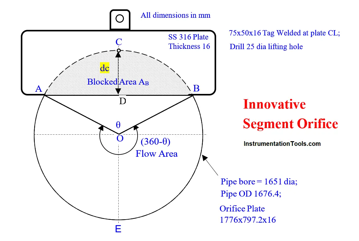
Innovative Segment Orifice

Thanks to unsticking enabled chord distance, he calculated, the workshop cut the orifice plate opening and delivered the orifice plate for use.

Benefits

The plant realized the previous problem explained the innovation of just welding a plate in the pipe cut slot with the sharp edge 55 mm away from the pipe horizontal diameter line. 

The plant realized all the Instrument Previous Problem discussed benefits

Author: S. Raghava Chari

Do you face any similar issues? Share with us through the below comments section.

If you liked this article, then please subscribe to our YouTube Channel for Instrumentation, Electrical, PLC, and SCADA video tutorials.

You can also follow us on Facebook and Twitter to receive daily updates.

Read Next:

  • Pressure Switch Screwed Cover
  • Too Low-Temperature Readings
  • Pressure Switch Screwed Cover
  • Thermowell Shank to Flange Leaks
  • Magnetic Flow Meter Liner Damaged
Don't Miss Our Updates
Be the first to get exclusive content straight to your email.
We promise not to spam you. You can unsubscribe at any time.
Invalid email address
You've successfully subscribed !

Continue Reading

Safety Liquid Ammonia Disconnect threatens NH3 Vapor Spill
Failing Weigh Feeders and Mechanical Variable Speed Drives (VSD)
Transformers Coolers Weld Joints Oil Oozes Were Eye Sores
Control Valves – Repeat Actuator Diaphragm Bursts
Fire burnt Ammonia Converter Thermocouples Problem
Fan Motor Frequent Journal Bearing Failures Posed Plant Outages
Share This Article
Facebook Whatsapp Whatsapp LinkedIn Copy Link
Share
Leave a Comment

Leave a Reply Cancel reply

Your email address will not be published. Required fields are marked *

Stay Connected

128.3kFollowersLike
69.1kFollowersFollow
210kSubscribersSubscribe
38kFollowersFollow

Categories

Explore More

Plant Air Storage Tank Pressure Fluctuations Root Cause Analysis
Solving Control Valve Hunting: Instrument Troubleshooting
Seal Pressure Instruments Root Cause Analysis
Root Cause Analysis – Burst Transformers and 11 kV Input Breakers
Gas Cooler Re-tubing Done Successfully (Root Cause Analysis)
Erratic H2 Flow Rotameter
Mechanical Temperature Indicators (MTI) Problem
An Indian Plants all turbines’ low Vacuum & Saudi Plant turbo-compressor only

Keep Learning

Bently Nevada Proximity Probe

Root Cause Analysis for Vibration Probe Not Responding

Instrumentation Engineering Root Cause Analysis

Instrumentation Engineering Problems Solved – Root Cause Analysis

Target Flow Transmitter Problem

Target Flow Transmitters Failed the Very Midnight

11 KV Bus A to Bus B Phase Check Problem

11 KV Bus A to Bus B Phase Check Problem

Electrical Engineering Problems - Root Cause Analysis

30 Electrical Engineering Problems – Root Cause Analysis

Fired Boiler Induced Draft Fan (IDF) Failures

Fired Boiler Induced Draft Fan (IDF) Failures Upset all Plants Operations

RF and RTJ Flange Installed Gasket

Flange Joint Errors shutdowns root cause analyzed and eliminated

Pressure Correction Pneumatic Instrumentation

Pressure Correction Pneumatic Instrumentation

Learn More

Simatic Prosave HMI

How to Backup and Restore from Simatic Prosave HMI?

Peak Inverse Voltage of Center Tap Rectifier

Peak Inverse Voltage of Center Tap Rectifier

Difference Between Open Circuit and Close Circuit

Difference Between Open Circuit and Close Circuit

Pressure Transmitter Installation

Field Instruments Mounting brackets

CNC Machining vs 3D Printer

CNC Machining vs 3D Printer – What is the difference?

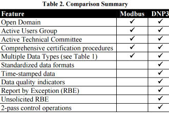
Modbus Vs DNP3

Difference between Modbus and DNP3 Communication Protocols

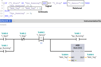
Introduction to SCL Programming in Siemens PLC

Types of Expressions in the SCL Language of the Tia Portal

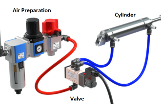
Basic Pneumatic System

Pneumatic Handbook

Menu

  • About
  • Privacy Policy
  • Copyright

Quick Links

  • Learn PLC
  • Helping Hand
  • Part Time Job

YouTube Subscribe

Follow US
All rights reserved. Reproduction in whole or in part without written permission is prohibited.
Welcome Back!

Sign in to your account

Username or Email Address
Password

Lost your password?