Modbus and DNP are both byte-oriented protocols. Modbus is an application layer protocol, while DNP3 contains Application and Data Link Layers, with a pseudo-transport layer.
Both protocols are widely used over a variety of physical layers, including RS-232, RS- 422, RS-485, and TCP/IP. Modbus has a separate specification for use over TCP/IP (Modbus-TCP). With DNP, the protocol is simply encapsulated within TCP/IP.
History
Modbus was developed in the process-control industry by Modicon in 1979. It was originally designed as a simple way to transfer data between controls and sensors via RS- 232 interfaces. Modbus now supports other communication media, including TCP/IP.
Modbus is now an open standard, administered by the Modbus-IDA (www.modbusida.com).
The Distributed Networking Protocol (DNP) was originally developed by Westronic, Inc. (now GE Harris) in 1990. The “DNP 3.0 Basic 4” protocol specification document set was released into the public domain in 1993, and ownership of the protocol was given to the newly formed DNP Users Group in October 1993. DNP was specifically developed for use in Electrical Utility SCADA Applications. It is now the dominant protocol in electrical utility SCADA systems, and is gaining popularity in other industries, including Oil & Gas, Water, and Waste Water.
Data Types
Modbus devices typically permit access to the inputs and outputs on a Programmable Logic Controller. The Modbus protocol standard does not specify how the 16-bit register values are sent. They may be sent high-byte first or low-byte first, signed or unsigned. Successive registers may even be combined to create floating point numbers.
Many Modbus device manufacturers add custom extensions to their devices to extend the functionality beyond that provided by standard Modbus. This and the common use of outputs as inputs sometimes makes it quite difficult to make even simple Modbus devices inter-operate.
Since the data types are not strictly defined, knowledge of how the device sends data is required in order to interpret the value that is sent. For example, in order to be assured of reading all devices, a Master station must be configurable to read either high byte first or low byte first data. This adds an additional step of complexity to the Master station setup.
Modbus point numbers are often broken up into special ranges (e.g., Holding Registers have addresses 40001 to 49999). Because Modbus supports the concept of reading back the value of an output, most Modbus devices only implement “output” type data. With this implementation, all inputs are read and addressed as if they were outputs.
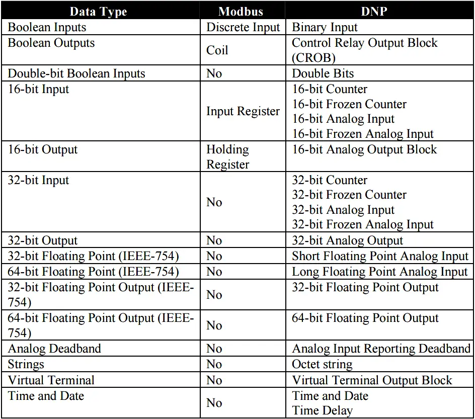
The DNP specification defines a large number of data types. Within each type multiple variations may be supported. These variations may describe whether the data are sent as 16-bit or 32-bit integral values; 32-bit or 64-bit floating point values; with or without timestamps; and with our without quality indicators (flags).
A comparison of Modbus and DNP3 data types is shown in Table 1.
Reading Data (Inputs)
Modbus reads values from ranges of inputs (and/or outputs) by issuing a single request to read each range or type. All data are treated as “present value”. Standard Modbus does not have a concept of events (transitory indications) or time. Any data that is not collected by reading it is lost when new field data updates it.
The DNP3 specification supports multiple methods of reading inputs individually or as a group. For example, multiple types of data can be encapsulated in a single message to improve efficiency. Time stamps and data quality information can also be included.
DNP3 also supports change events. By polling for change events, the Master station can reduce overall traffic on the line, as only values that have changed are reported. This is commonly called Report by Exception (RBE).
To further improve efficiency, DNP3 also supports unsolicited reporting. With unsolicited reporting, Slave devices can send updates as values change, without having to wait for a poll from the Master.
The Master station can easily process change event data (polled or unsolicited) because the report includes the data type and variation, point number, value, and (optionally) time stamp and quality indicators. Time-tagged change events can be used to easily create a sequence of events log.
Control Operations (Outputs)
Modbus supports control operations via its read/write data types (Coils and Holding Registers).
DNP3 supports control operations via output object groups (CROB and Analog Output Blocks). DNP3 output objects are also read/write; reading the output object returns the output stats (i.e., the last command that was written). The actual value of the control point can be monitored via a Binary or Analog input.
DNP3 also supports high-security two-step control operations. With these operations, a “Select” request is sent first. Once it is confirmed by the Slave device, the actual “Operate” request is sent. The select/operate sequence insures the integrity of the control command.
DNP3 also supports a variety functions commonly used on control applications, such as pulsed and paired outputs. The quality flags reported by DNP3 give important output quality status information, including whether the point is offline, if it is being controlled locally (e.g., local override), etc
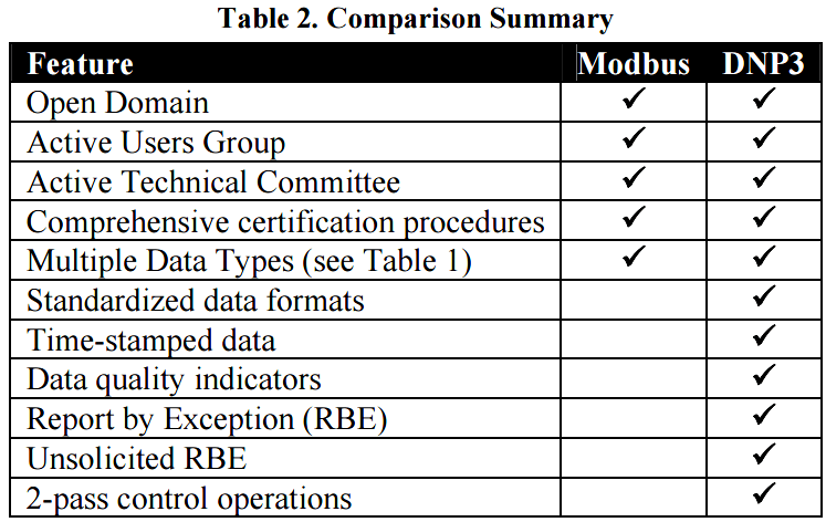
Summary
Table 2 provides a brief summary of Modbus and DNP3.
The primary advantage of Modbus is its simplicity for small devices and the very large range of devices that have some sort of Modbus interface. It is widely used in process control and SCADA systems.
DNP3 is specifically designed for use in SCADA applications. It is highly standardized, with relatively high compatibility and inter-operability between devices from different manufacturers.
Both DNP3 and Modbus have independent Technical committees that are working to ensure interoperability and create standards for new functionality.
Article Source: trianglemicroworks