Learn about the sequential program concept in CX-Programmer software and how it can be applied to automatic vacuum cleaners using Omron PLC.
Automatic Vacuum Cleaner
The PLC system can Run in 3 modes – Manual, Auto, and Timer. In “Manual” mode the Vaccum Cleaner can be turned ON using the Button. In “Auto” mode Vaccum Cleaner will turn ON when the dust level in the room exceeds the “Set value” limit. In “Timer” mode Vaccum Cleaner will turn ON sequentially, the Vaccum Cleaner will be ON for 5 seconds and will be OFF for 5 seconds.
This PLC program has 4 buttons, the START_SYSTEM (0.00) button is used to turn ON the system, the STOP_SYSTEM (0.01) button is used to turn OFF the system, the SELECTOR_MODE (0.02) button is used to select the mode to be Run, and the VACCUM_CLEANER_BUTTON (0.03) button is used to turn ON the output VACCUM_CLEANER (100.00) when the system is Running in Manual mode.
The PLC program has 3 sequences stored in memory word MODE (D0). If SELECTOR_MODE (0.02) button is Pressed, the value in the memory word MODE (D0) will increase (+1), and when the value is equal to “3” the memory word MODE (D0) will be reset to zero “0”.
In sequence 1, the memory word MODE (D0) will be zero “0” and the system in “Manual” mode.
When in “Manual” mode the VACCUM_CLEANER (100.00) output can only be ON if the VACCUM_CLEANER_BUTTON (0.03) button is Pressed.
In sequence 2, the memory word MODE (D0) will have a value of one “1” and the system in “Timer” mode.
In this Mode, the VACCUM_CLEANER (100.00) output will be ON sequentially, the Vaccum Cleaner will be ON for 5 seconds, and will be OFF for 5 seconds.
In sequence 3, the memory word MODE (D0) will have a value of two “2” and the system in “Auto” mode.
In this mode, the VACCUM_CLEANER (100.00) output will be ON if the value in memory word DUST_LEVEL (D10) is greater than or equal to “35”.

PLC Inputs/Outputs
| Comment | Input (I) | Output (Q) | Memory Bits | Memory Word | Timers |
| START_SYSTEM | 0.00 | ||||
| STOP_SYSTEM | 0.01 | ||||
| SELECTOR_MODE | 0.02 | ||||
| VACCUM_CLEANER_BUTTON | 0.03 | ||||
| VACCUM_CLEANER | 100.00 | ||||
| MODE | D0 | ||||
| DUST_LEVEL | D10 | ||||
| TIMER1 | T0000 | ||||
| TIMER2 | T0001 | ||||
| SYSTEM_ON | W0.00 | ||||
| IR_MANUAL_MODE | W0.01 | ||||
| IR_TIMER_MODE | W0.02 | ||||
| IR_AUTO_MODE | W0.03 |
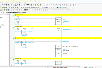
Programming in Omron PLC
RUNG 0 (SYSTEM ON)
In this Rung, when START_SYSTEM(0.00) button is pressed, the memory bit SYSTEM_ON (W0.00) changes to HIGH state. Because it uses latching, the memory bit SYSTEM_ON (W0.00) remains in the HIGH state even though the START_SYSTEM (0.00) button has been Released.
The memory bit SYSTEM_ON (W0.00) will become a LOW state if the STOP_SYSTEM (0.01) button is Pressed.

RUNG 1 (MODE)
In this rung, if the NO contact memory bit SYSTEM_ON (W0.00) is in a HIGH state and the SELECTOR_MODE (0.02) button is Pressed (once), then the value in memory word MODE (D0) will increase (+1).
RUNG 2 (MANUAL MODE)
When the NO contact memory bit SYSTEM_ON (W0.00) is in a HIGH state and memory word MODE (D0) is equal to zero “0” and the VACCUM_CLEANER_BUTTON (0.03) button is Pressed, the memory bit IR_MANUAL_MODE (W0.01) will change to the HIGH state.
RUNG 3 (TIMER MODE)
In this Rung, when the NO contact of memory bit SYSTEM_ON (W0.00) in HIGH state and the memory word MODE (D0) has a value equal to “1”, then the memory bit IR_TIMER_MODE (W0.02) bit will be in HIGH state. The timer instruction TIMER1 (T0000) will Start counting up to 5 seconds and timer TIMER2 (T0001) will count up to 10 seconds.
When the timer TIMER1 (T0000) finishes counting, the memory bit IR_TIMER_MODE (W0.02) will change to a LOW state due to the interlock of timer TIMER1 (T0000).
When timer TIMER2 (T0001) finishes counting, timer TIMER1 (T0000) will be OFF due to the interlock of timer TIMER2 (T0001), and the memory bit IR_TIMER_MODE (W0.02) will change to HIGH state again. This situation will continue to repeat itself.

RUNG 4 (AUTO MODE)
In this Rung, when the NO contact memory bit SYSTEM_ON (W0.00) is in the HIGH state and the memory word MODE (D0) has a value equal to zero “0” and the memory word DUST_LEVEL (D10) has a value greater than or equal to “35”, then memory bit IR_AUTO_MODE (W0.03) will change to the HIGH state.
RUNG 5 (RESET MODE)
In this Rung, when the NO contact memory bit SYSTEM_ON (W0.00) is in the HIGH state and the memory word MODE (D0) has a value equal to zero “3”, then the MOV(021) instruction will move the zero value “0” to memory word MODE (D0) so that the system resets back to “Manual” mode.

RUNG 6 (OUT VACUUM CLEANER)
The VACCUM_CLEANER (100.00) output will be ON if the NO contact of memory bit IR_MANUAL_MODE (W0.01) or IR_TIMER_MODE (W0.02) or IR_AUTO_MODE (W0.03) is in HIGH state.
Read Next:
- Studio 5000 Motor Running Hours PLC Logic
- STAR-DELTA Auto And Manual PLC Program
- PLC 1 Button To Activate 4 Different Machines
- Electric Motor Forward Reverse PLC Logic
- Product Painting with Omron PLC Program