Inst ToolsInst ToolsInst Tools
  • Courses
  • Automation
    • PLC
    • Control System
    • Safety System
    • Communication
    • Fire & Gas System
  • Instrumentation
    • Design
    • Pressure
    • Temperature
    • Flow
    • Level
    • Vibration
    • Analyzer
    • Control Valve
    • Switch
    • Calibration
    • Erection & Commissioning
  • Interview
    • Instrumentation
    • Electrical
    • Electronics
    • Practical
  • Q&A
    • Instrumentation
    • Control System
    • Electrical
    • Electronics
    • Analog Electronics
    • Digital Electronics
    • Power Electronics
    • Microprocessor
  • Request
Search
  • Books
  • Software
  • Projects
  • Process
  • Tools
  • Basics
  • Formula
  • Power Plant
  • Root Cause Analysis
  • Electrical Basics
  • Animation
  • Standards
  • 4-20 mA Course
  • Siemens PLC Course
Reading: Servo Tank Gauges Working Principle
Share
Notification Show More
Font ResizerAa
Inst ToolsInst Tools
Font ResizerAa
  • Courses
  • Design
  • PLC
  • Interview
  • Control System
Search
  • Courses
  • Automation
    • PLC
    • Control System
    • Safety System
    • Communication
    • Fire & Gas System
  • Instrumentation
    • Design
    • Pressure
    • Temperature
    • Flow
    • Level
    • Vibration
    • Analyzer
    • Control Valve
    • Switch
    • Calibration
    • Erection & Commissioning
  • Interview
    • Instrumentation
    • Electrical
    • Electronics
    • Practical
  • Q&A
    • Instrumentation
    • Control System
    • Electrical
    • Electronics
    • Analog Electronics
    • Digital Electronics
    • Power Electronics
    • Microprocessor
  • Request
Follow US
All rights reserved. Reproduction in whole or in part without written permission is prohibited.
Inst Tools > Blog > Level Measurement > Servo Tank Gauges Working Principle

Servo Tank Gauges Working Principle

Last updated: December 31, 2017 3:13 pm
Editorial Staff
Level Measurement
1 Comment
Share
3 Min Read
SHARE

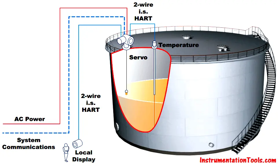
Tank gauging is the generic name given to the measurement of liquids (product) in bulk storage tanks with the aim of quantifying how much product is in the tank, “gauging the contents of a tank”. Today, the oil & gas industry uses the static measurement of the tank contents to account for product stored and product moved into and out of the tank.

There are many instruments and systems available that can provide the combination of measurements that will allow an accurate quantity assessment and, hence, good inventory management. In Practice, we use both Radar and Servo Level Transmitters for Tank Gauges.

Servo Tank Gauges Principle

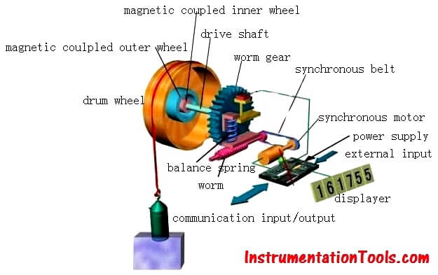
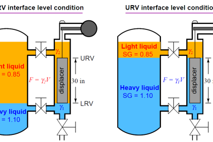
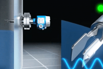
The Servo tank gauging system is based on the principle of displacement measurement. A small displacer is accurately positioned in the liquid medium using a servo motor. The displacer is suspended on a measuring wire that is wound onto a finely grooved drum housing within the instrument.

Servo Tank Gauge Level Principle

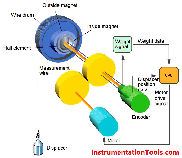
The drum is driven via coupling magnets, which are completely separated by the drum housing. Outer magnets are connected to the wire drum whilst the inner magnets are connected to the drive motor. As the magnets turn, the magnetic attraction causes the outer magnets to turn as well, resulting in turning the entire drum assembly. The weight of the displacer on the wire creates a torque on the outer magnets generating the change of magnetic flux. These changes generated between the drum assembly are detected by a unique electromagnetic transducer on the inner magnet. The drive motor is actuated to balance the voltage generated by the variations of magnetic flux to equal the reference voltage defined by the operating command.

Servo Level Transmitter Working Principle

When the displacer is lowered and touches the liquid, the weight of the displacer is reduced because of the buoyant force of the liquid. As a result, the torque in the magnetic coupling is changed and this change is measured usng Hall sensor, which are temperature compensated. The signal, an indication of the position of the displacer, is sent to the motor control circuit. As the liquid level rises and falls, the position of the displacer is adjusted by the drive motor. The rotation of the wire drum is precisely evaluated to determine the level value, which is accurate to an outstanding +/‐ 0.7 mm.

Servo Tank Gauge System Operation

Don't Miss Our Updates
Be the first to get exclusive content straight to your email.
We promise not to spam you. You can unsubscribe at any time.
Invalid email address
You've successfully subscribed !

Continue Reading

Differential Pressure (DP) Level transmitter Installed Below Tapping Point
DP Level Measurement Problems
Purpose of Tank Gauging Level Measurement
How to Measure Density using DP Transmitter?
Wrong Installation of Horn Type Radar Level Transmitter on Sloping Tank
The 5 ways Ultrasonic Sensors Work
Share This Article
Facebook Whatsapp Whatsapp LinkedIn Copy Link
Share
1 Comment
  • MINESHKUMAR says:
    April 27, 2018 at 3:07 pm

    ERS(ELECTRONIC REMOTE SENSOR ) TYPE LEVEL TRANSMITTER, IF ANY BODY HAVE PLEASE SEND ME DETAIL. NOW PROBLEM IS HART NOT CONNECT. DISPLAY SHOW DEVICE NOT FOUND. WE CHECK OUR SIDE IS CLEAR BUT THEN ALSO STILL PROBLEM STAND THEIR.

    ANY BODY HAS SOLUTION LET ME INFORM [email protected]

    Reply

Leave a Reply Cancel reply

Your email address will not be published. Required fields are marked *

Stay Connected

128.3kFollowersLike
69.1kFollowersFollow
210kSubscribersSubscribe
38kFollowersFollow

Categories

Explore More

Cat and Mouse type Level Indicator
Rotary Level Switch Working principle Animation
DP Level Transmitter Calibration for Diaphragm Seal with Capillary
Basics of Hydrostatic Level Measurement
Ultrasonic Level Transmitter Animation
DP Level Transmitters Compensation Techniques
Calibrating Level Transmitter with Remote Seals
Level Gauge Interface & Temperature Problems

Keep Learning

Hydrostatic Level Measurement

Hydrostatic Level Measurement

Comparison of Level Meters - Level Measurement Instruments

Comparison of Level Meters – Level Measurement Instruments

Closed-Tank-DP-Type-Level-Measurement-with-wet-leg-and-transmitter-installed-below-tapping-point

Level Measurement with Wet leg and Installed Below Tapping Point

Open Tank DP Level Measurement

Open Tank DP Level Transmitter Calculations

How to Install Ultrasonic Level Transmitters 5

How to Install Ultrasonic Level Transmitters

Radar and Ultrasonic Level Transmitter Problems Troubleshooting

Radar and Ultrasonic Level Transmitter Practical Problems Troubleshooting

Tilt Level Switch Working Animation

Radiation Level Measurement Principle

Radiation Level Measurement

Learn More

Multi-Cartridge Filter

Cartridge Filters

Data Protection Tips

8 Data Protection Tips For Businesses And Individuals

direct and reverse acting PID controller Tuning

Recognizing an Over-Tuned PID Controller by Phase Shift

Address Resolution Protocol (ARP)

What is the Address Resolution Protocol? – Types of ARP

Pressure Gauges with Diaphragm Sensor Principle

Pressure Gauges with Diaphragm Sensor Principle

Jet Pump

What is a Jet Pump? – Principle, Types, Comparison

Flow Measurement Quiz

Flow and Level Measurement Quiz

UX Design

How to Achieve Sustainability in UX Design and Make a Difference?

Menu

  • About
  • Privacy Policy
  • Copyright

Quick Links

  • Learn PLC
  • Helping Hand
  • Part Time Job

YouTube Subscribe

Follow US
All rights reserved. Reproduction in whole or in part without written permission is prohibited.
Welcome Back!

Sign in to your account

Username or Email Address
Password

Lost your password?