To tune a feedback control system means to adjust parameters in the controller to achieve robust control over the process. “Robust” in this context is usually defined as stability of the process variable despite changes in load, fast response to changes in setpoint, minimal oscillation following either type of change, and minimal offset (error between setpoint and process variable) over time.
“Robust control” is far easier to define than it is to achieve. With PID (Proportional-Integral- Derivative) control being the most common feedback control algorithm used in industry, it is important for all instrumentation practitioners to understand how to tune these controllers effectively and with a minimum investment of time.
Different types of processes, having different dynamic (time-dependent) behaviors, require different levels of proportional, integral, and derivative control action to achieve stability and robust response. It is therefore imperative for anyone seeking to tune a PID controller to understand the dynamic nature of the process being controlled. For this reason, the chapter begins with an exploration of common process characteristics before introducing techniques useful in choosing practical P, I, and D tuning parameter values.
Process Characteristics
Perhaps the most important rule of controller tuning is to know the process before attempting to adjust the controller’s tuning. Unless you adequately understand the nature of the process you intend to control, you will have little hope in actually controlling it well. This section of the book is dedicated to an investigation of different process characteristics and how to identify each.
Quantitative PID tuning methods attempt to map the characteristics of a process so good PID parameters may be chosen for the controller. The goal of this section is for you to understand various process types by observation and qualitative analysis so you may comprehend why different tuning parameters are necessary for each type, rather than mindlessly following a step-by-step PID tuning procedure.
The three major classifications of process response are self-regulating, integrating, and runaway. Each of these process types is defined by its response to a step-change in the manipulated variable (e.g. control valve position or state of some other final control element). A “self-regulating” process responds to a step-change in the final control element’s status by settling to a new, stable value.
An “integrating” process responds by ramping either up or down at a rate proportional to the magnitude of the final control element’s step-change. Finally, a “runaway” process responds by ramping either up or down at a rate that increases over time, headed toward complete instability without some form of corrective action from the controller.
Self-regulating, integrating, and runaway processes have very different control needs. PID tuning parameters that may work well to control a self-regulating process, for example, will not work well to control an integrating or runaway process, no matter how similar any of the other characteristics of the processes may be (Note). By first identifying the characteristics of a process, we may draw some general conclusions about the P, I, and D setting values necessary to control it well.
Perhaps the best method for testing a process to determine its natural characteristics is to place the controller in manual mode and introduce a step-change to the controller output signal. It is critically important that the loop controller be in manual mode whenever process characteristics are being explored. If the controller is left in the automatic mode, the response seen from the process to a setpoint or load change will be partly due to the natural characteristics of the process itself and partly due to the corrective action of the controller.
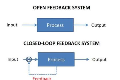
The controller’s corrective action thus interferes with our goal of exploring process characteristics. By placing the controller in “manual” mode, we turn off its corrective action, effectively removing its influence by breaking the feedback loop between process and controller, controller and process. In manual mode, the response we see from the process to an output (manipulated variable) or load change is purely a function of the natural process dynamics, which is precisely what we wish to discern.
A test of process characteristics with the loop controller in manual mode is often referred to as an open-loop test, because the feedback loop has been “opened” and is no longer a complete loop. Open-loop tests are the fundamental diagnostic technique applied in the following subsections.+
Note : To illustrate, self-regulating processes require significant integral action from a controller in order to avoid large offsets between PV and SP, with minimal proportional action and no derivative action. Integrating processes, in contrast, may be successfully controlled primarily on proportional action, with minimal integral action to eliminate offset.
Runaway processes absolutely require derivative action for dynamic stability, but derivative action alone is not enough: some integral action will be necessary to eliminate offset. Even if knowledge of a process’s dominant characteristic does not give enough information for us to quantify P, I, or D values, it will tell us which tuning constant will be most important for achieving stability.
Also Read :
