Based on the construction of internal moving parts, the spool valve is most widely used in hydraulic systems.
A spool is a cylindrical unit that has a large diameter land, machined to slide in a close-fitting bore of the directional control valve body. The radial clearance is normally less than 0.02 mm.
Spools are integrated into the directional control valve body are used to provide different flow paths. This is implemented by the opening and closing of connected ports by the spool lands.
Types of Spool Valves
There are two types of spool valves.
- Rotary
- Sliding.
Rotary Spool Valve
Rotary Spool valves, so-called because it is the rotational movement of a spool that opens or closes a fluid passage.
Rotary spool valves are normally manually operated and used for all small flow rates at low pressures.
Rotary spool valve finds used extensively in the machine tools industry.
Sliding Spool Valve
Sliding spool valves are most popular and generally used in the industry. They are made for all types of the control systems, such as for maximum flow rates and pressures.
The sliding spools may be operated through different modes like
- Mechanical actuation,
- Manual operation,
- Pneumatic operation,
- Hydraulic or pilot control, and
- Electrical means.
Construction of Spool Valve
These valves have a cylindrical shaft called a “spool”, which slides into a machined bore in the directional control valve housing. The housing has fluid inlet and outlet ports to connect the directional control valve to the hydraulic circuit.
The sliding spool-type directional control valves can be designed with unlike combinations of spool and housing. The lands of the spool divide the housing bore into a series of separate chambers.
The ports of the valve body lead into these chambers and the position of the spool determines the nature of interconnection between the ports.
Spool-type valves are extensively used in mobile hydraulic systems because these types of valves can easily be shifted to two, three, or more positions to direct fluid between different combinations of inlet and outlet ports.
With regard to their flow-directing states, there are four commonly applied neutral position designs.
- Closed-center
- Open center
- Tandem center
- Float center
Many more configurations are available, but a few basic configurations are discussed here.
All the above designs will connect the flow pathway of P-to-A and B-to-T when shifting the spool to the left. The Spool movement when shifting to the right will connect flow pathways P-to-B and A-to-T.
Two-position Directional Control Valves
The figure below shows a four-way, two-position, spring return, manually lever operated, and sliding spool-type directional control valve.
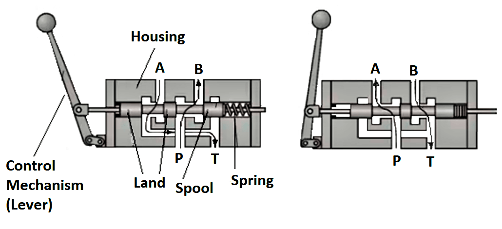
At the normal position (non-actuated position) initiates the flow paths P – B and A – T.
Upon actuated by the lever the flow paths P – A and B – T are maintained.
Applications
- A most common use for the two-position valve is in a cylinder application which only requires the cylinder to extend or retract to its fullest positions.
- Another application would be in hydraulics motors, which only run forward or reverse directions.
Three-position Directional Control Valves
A three-position valve is similar in operation to a two-position valve but can be stopped in a third or centered position.
Depending on the spool design of the center position (or neutral position), the flow may or may not be possible,
Closed Center Valve
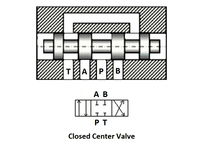
In the closed center valve, all the ports are under a normally closed condition. Ports are isolated from each other.
A closed center valve can be used where it is desired that the actuator must remain locked-in state even while the pump discharge is continued to charge an accumulator or operate some other actuator.
Applications
This type of valve is used in hydraulic systems, with a variable displacement pump, and generally in load sensing systems.
Open Center Valve
It is normally open conditions to all ports. It means that all the ports in the valve are connected to their neutral position.
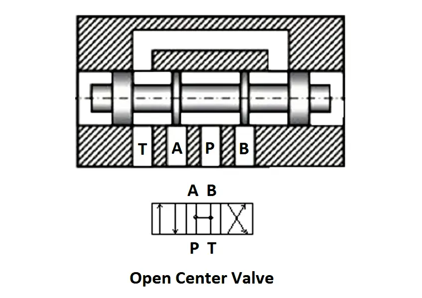
In the center position, this spool vale cannot support the load against gravity. Also, it is not possible to lock the actuator at desired places.
Applications
- Open center valves can be used to control rotary actuators in either direction.
- The open center valve is used in hydraulic systems with a fixed displacement pump.
Tandem Center Valve
Connects the pump (P) and tank port (T) to allow hydraulic pump discharge flow to return to the tank freely.
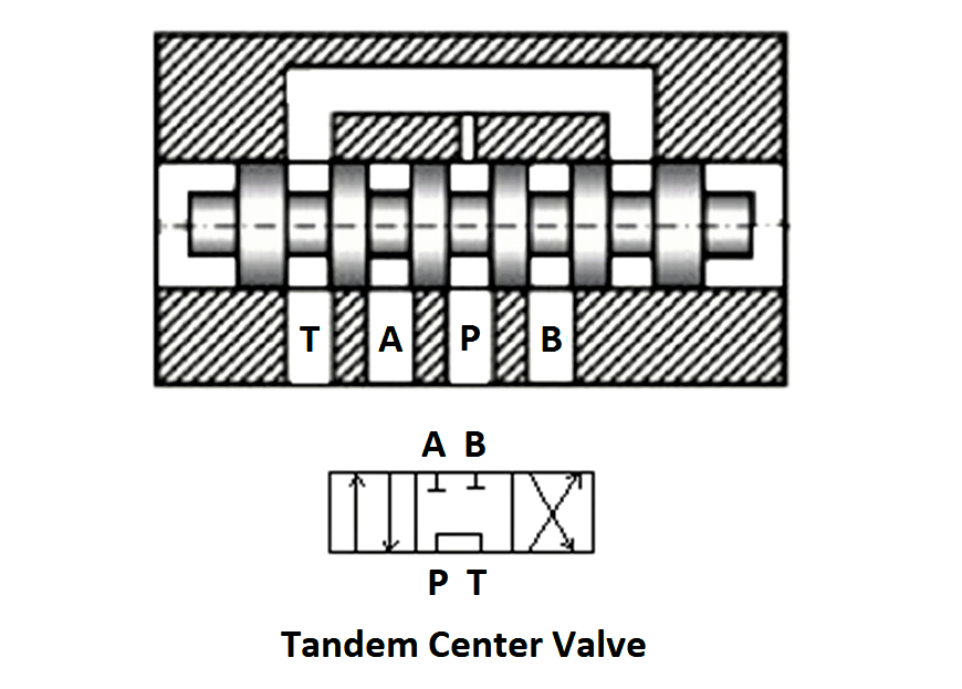
The spool is at a neutral state, blocks both working ports (A, B) to keep the pressure on both sides of an actuator to hold at the same state.
Float Center Valve
It connects both working ports to the tank port to permit the working flow to freely return to the tank.
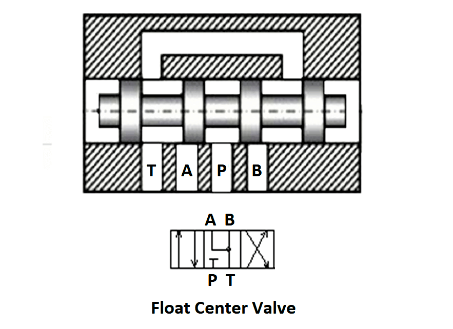
But it blacks the pump port to the tank port to prevent pump flow from being drained to the tank at the neutral position.
Applications
It is used in hydraulic systems powered by a variable displacement pump.
Reference: Basics of Hydraulic Systems by Qin Zhang
If you liked this article, then please subscribe to our YouTube Channel for Instrumentation, Electrical, PLC, and SCADA video tutorials.
You can also follow us on Facebook and Twitter to receive daily updates.
Read Next: