Before we begin our discussion on process control, we must define a few key terms. First, we have what is known as the process: the physical system we wish to monitor and control.
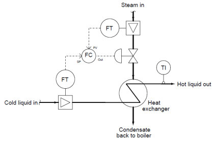
For the sake of illustration, consider a heat exchanger that uses high-temperature steam to transfer heat to a lower temperature liquid.
Heat exchangers are used frequently in the chemical industries to maintain the necessary temperature of a chemical solution, so the desired blending, separation, or reactions can occur.
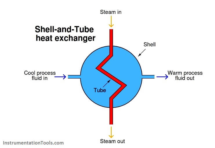
A very common design of heat exchanger is the “shell-and-tube” style, where a metal shell serves as a conduit for the chemical solution to flow through, while a network of smaller tubes runs through the interior of the shell, carrying steam or some other heat-transfer fluid.
The hotter steam flowing through the tubes transfers heat energy to the cooler process fluid surrounding the tubes, inside the shell of the heat exchanger:
In this case, the process is the entire heating system, consisting of the fluid we wish to heat, the heat exchanger, and the steam delivering the required heat energy.
In order to maintain steady control of the process fluid’s exiting temperature, we must find a way to measure it and represent that measurement in signal form so it may be interpreted by other instruments taking some form of control action.
In instrumentation terms, the measuring device is known as a transmitter, because it transmits the process measurement in the form of a signal.
Transmitters are represented in process diagrams by small circles with identifying letters inside, in this case, “TT,” which stands for Temperature Transmitter:
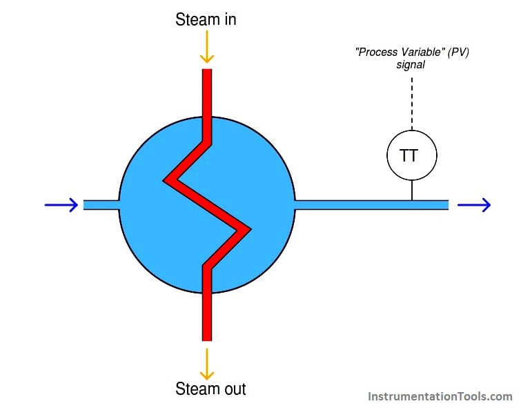
The signal output by the transmitter (represented by the “PV” dashed line), representing the heated fluid’s exiting temperature, is called the process variable.
Like a variable in a mathematical equation that represents some story-problem quantity, this signal represents the measured quantity we wish to control in the process.
In order to exert control over the process variable, we must have some way of altering fluid flow through the heat exchanger, either of the process fluid, the steam, or both.
Generally, it makes more sense to alter the flow of the heating medium (the steam), and let the process fluid flow rate be dictated by the demands of the larger process.
If this heat exchanger were part of an oil refinery unit, for example, it would be far better to throttle steam flow to control oil temperature rather than to throttle the oil flow itself, since altering the oil’s flow will also affect other process variables upstream and downstream of the exchanger.
Ideally, the heat exchanger temperature control system would provide consistent temperature of the exiting oil, for any given incoming oil temperature and flow-rate of oil through it.
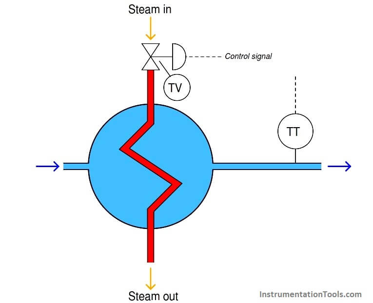
One convenient way to throttle steam flow into the heat exchanger is to use a control valve (labeled “TV” because it is a Temperature Valve). In general terms, a control valve is known as a final control element.
Other types of final control elements exist (servo motors, variable-flow pumps, and other mechanical devices used to vary some physical quantity at will), but valves are the most common, and probably the simplest to understand.
With a final control element in place, the steam flow becomes known as the manipulated variable, because it is the quantity we will manipulate in order to gain control over the process variable:
Valves come in a wide variety of sizes and styles. Some valves are hand-operated: that is, they have a “wheel” or other form of manual control that may be moved to “pinch off” or “open up” the flow passage through the pipe.
Other valves come equipped with signal receivers and positioner devices, which move the valve mechanism to various positions at the command of a signal (usually an electrical signal, like the type output by transmitter instruments).
This feature allows for remote control, so a human operator or computer device may exert control over the manipulated variable from a distance.
In the previous illustration, the steam control valve is equipped with such an electrical signal input, represented by the “control signal” dashed line.
This brings us to the final component of the heat exchanger temperature control system: the controller.
This is a device designed to interpret the transmitter’s process variable signal and decide how far open the control valve needs to be in order to maintain that process variable at the desired value.
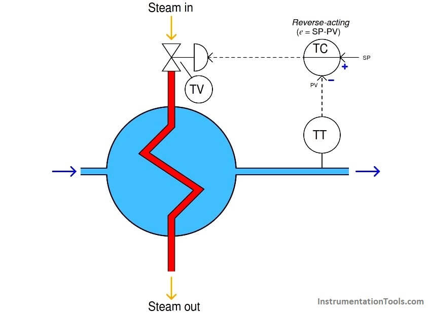
Here, the circle with the letters “TC” in the center represents the controller. Those letters stand for Temperature Controller, since the process variable being controlled is the process fluid’s temperature.
Usually, the controller consists of a computer making automatic decisions to open and close the valve as necessary to stabilize the process variable at some predetermined setpoint.
Note that the controller’s circle has a solid line going through the center of it, while the transmitter and control valve circles are open.
An open circle represents a field-mounted device according to the ISA standard for instrumentation symbols, and a single solid line through the middle of a circle tells us the device is located on the front of a control panel in a main control room location.
So, even though the diagram might appear as though these three instruments are located close to one another, they in fact may be quite far apart.
Both the transmitter and the valve must be located near the heat exchanger (out in the “field” area rather than inside a building), but the controller may be located a long distance away where human operators can adjust the setpoint from inside a safe and secure control room.
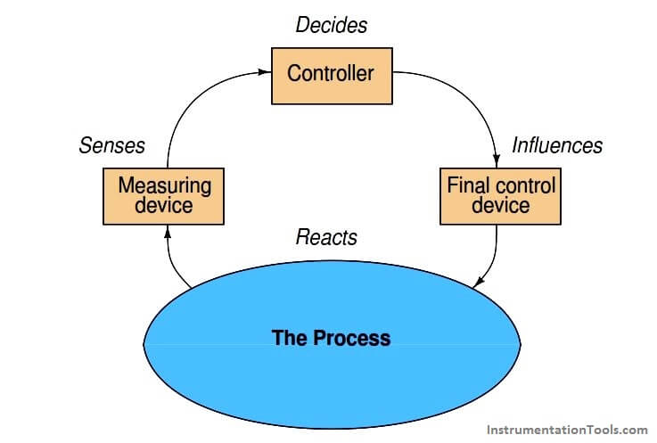
These elements comprise the essentials of a feedback control system: the process (the system to be controlled), the process variable (the specific quantity to be measured and controlled), the transmitter (the device used to measure the process variable and output a corresponding signal), the controller (the device that decides what to do to bring the process variable as close to setpoint as possible), the final control element (the device that directly exerts control over the process), and the manipulated variable (the quantity to be directly altered to effect control over the process variable).
Feedback control may be viewed as a sort of information “loop,” from the transmitter (measuring the process variable), to the controller, to the final control element, and through the process itself, back to the transmitter. Ideally, a process control “loop” not only holds the process variable at a steady level (the setpoint), but also maintains control over the process variable given changes in setpoint, and even changes in other variables of the process:
Specifically, the type of feedback we are employing here to control the process is negative or degenerative feedback.
The term “negative” refers to the direction of action the control system takes in response to any measured change in the process variable. If something happens to drive the process variable up, the control system will automatically respond in such a way as to bring the process variable back down where it belongs.
If the process variable happens to sag below setpoint, the control system will automatically act to drive the process variable back up to setpoint. Whatever the process variable does in relation to setpoint, the control system takes the opposite (inverse, or negative) action in an attempt to stabilize it at setpoint.
For example, if the unheated process fluid flow rate were to suddenly increase, the heat exchanger outlet temperature would fall due to the physics of heat transfer, but once this drop was detected by the transmitter and reported to the controller, the controller would automatically call for additional steam flow to compensate for the temperature drop, thus bringing the process variable back in agreement with the setpoint. Ideally, a well-designed and well-tuned control loop will sense and compensate for any change in the process or in the setpoint, the end result being a process variable value that always holds steady at the setpoint value.
The unheated fluid flow rate is an example of an uncontrolled, or wild, variable because our control system here has no ability to influence it. This flow is also referred to as a load because it “loads” or affects the process variable we are trying to stabilize.
Loads are present in nearly every controlled system, and indeed are the primary factor necessitating a control system at all. Referring back to our heat exchanger process again, we could adequately control the operating temperature of it with just a manually-set steam control valve if only none of the other factors (steam temperature, fluid flow rate, incoming fluid temperature, etc.) ever changed!
Many types of processes lend themselves to feedback control. Consider an aircraft autopilot system, keeping an airplane on a steady course heading despite the effects of loads such as sidewinds: reading the plane’s heading (process variable) from an electronic compass and using the rudder as a final control element to change the plane’s “yaw.”
An automobile’s “cruise control” is another example of a feedback control system, with the process variable being the car’s velocity, and the final control element being the engine’s throttle.
The purpose of a cruise control is to maintain constant driving speed despite the influence of loads such as hills, head-winds, tail-winds, and road roughness. Steam boilers with automatic pressure controls, electrical generators with automatic voltage and frequency controls, and water pumping systems with automatic flow controls are further examples of how feedback may be used to maintain control over certain process variables.
Modern technology makes it possible to control nearly anything that may be measured in an industrial process. This extends beyond the pale of simple pressure, level, temperature, and flow variables to include even certain chemical properties.
In municipal water and wastewater treatment systems, for example, numerous chemical quantities must be measured and controlled automatically to ensure maximum health and minimum environmental impact.
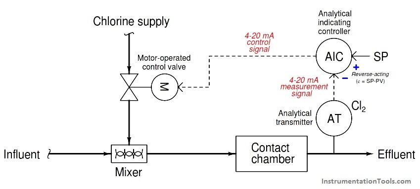
Take for instance the chlorination of treated wastewater, before it leaves the wastewater treatment facility into a large body of water such as a river, bay, or ocean. Chlorine is added to the water to kill any residual bacteria so they do not consume oxygen in the body of water they are released to.
Too little chlorine added, and not enough bacteria are killed, resulting in a high biological oxygen demand or BOD in the water which will asphyxiate the fish swimming in it. Too much chlorine added, and the chlorine itself poses a hazard to marine life.
Thus, the chlorine content must be carefully controlled at a particular setpoint, and the control system must take aggressive action if the dissolved chlorine concentration strays too low or too high:
Now that we have seen the basic elements of a feedback control system, we will concentrate on the algorithms used in the controller to maintain a process variable at setpoint.
For the scope of this topic, an “algorithm” is a mathematical relationship between the process variable and setpoint inputs of a controller, and the output (manipulated variable).
Control algorithms determine how the manipulated variable quantity is deduced from PV and SP inputs, and range from the elementary to the very complex. In the most common form of control algorithm, the so-called “PID” algorithm, calculus is used to determine the proper final control element action for any combination of input signals.
Diagnosing feedback control problems
One of the basic diagnostic strategies for any instrumentation system is to assess whether the input value(s) and output value(s) correspond for each instrument. We may apply this same strategy to each of the four elements of a feedback control “loop” to identify where the problem might exist. If you encounter one of these four system portions whose output does not correspond with its input, you know that portion of the system is faulted.
You can check each element of your feedback control loop by comparing its input with its output to see if each element is doing what it should. I recommend beginning with the controller (the decision-making element) because typically those values are the most easily monitored:
• Decision-making: Carefully examine the controller faceplate, looking at the values of PV, SP, and Output. Is the controller taking appropriate action to force PV equal to SP? In other words, is the Output signal at a value you would expect if the controller were functioning properly to regulate the process variable at setpoint? If so, then the controller’s action and tuning are most likely not at fault. If not, then the problem definitely lies with the controller.
• Sensing: Compare the controller’s displayed value for PV with the actual process variable value as indicated by local gauges, by feel, or by any other means of detection. If there is good correspondence between the controller’s PV display and the real process variable, then there probably isn’t anything wrong with the measurement portion of the control loop (e.g. transmitter, impulse lines, PV signal wiring, analog input of controller, etc.). If the displayed PV disagrees with the actual process variable value, then something is definitely wrong here.
• Influencing: Compare the controller’s displayed value for Output with the actual status of the final control element. If there is good correspondence between the controller’s Output display and the FCE’s status, then there probably isn’t anything wrong with the output portion of the control loop (e.g. FCE, output signal wiring, analog output of controller, etc.). If the controller Output value differs from the FCE’s state, then something is definitely wrong here.
• Reacting: Compare the process variable value with the final control element’s state. Is the process doing what you would expect it to? If so, the problem is most likely not within the process (e.g. manual valves, relief valves, pumps, compressors, motors, and other process equipment). If, however, the process is not reacting the way you would expect it to given the final control element’s state, then something is definitely awry with the process itself.