Inst ToolsInst ToolsInst Tools
  • Courses
  • Automation
    • PLC
    • Control System
    • Safety System
    • Communication
    • Fire & Gas System
  • Instrumentation
    • Design
    • Pressure
    • Temperature
    • Flow
    • Level
    • Vibration
    • Analyzer
    • Control Valve
    • Switch
    • Calibration
    • Erection & Commissioning
  • Interview
    • Instrumentation
    • Electrical
    • Electronics
    • Practical
  • Q&A
    • Instrumentation
    • Control System
    • Electrical
    • Electronics
    • Analog Electronics
    • Digital Electronics
    • Power Electronics
    • Microprocessor
Search
  • Books
  • Software
  • Projects
  • Process
  • Tools
  • Basics
  • Formula
  • Power Plant
  • Root Cause Analysis
  • Electrical Basics
  • Animation
  • Standards
  • 4-20 mA Course
  • Siemens PLC Course
Reading: Procedure for Connecting Allen Bradley PLC and PC – RS Logix 500
Share
Notification Show More
Font ResizerAa
Inst ToolsInst Tools
Font ResizerAa
  • Courses
  • Design
  • PLC
  • Interview
  • Control System
Search
  • Courses
  • Automation
    • PLC
    • Control System
    • Safety System
    • Communication
    • Fire & Gas System
  • Instrumentation
    • Design
    • Pressure
    • Temperature
    • Flow
    • Level
    • Vibration
    • Analyzer
    • Control Valve
    • Switch
    • Calibration
    • Erection & Commissioning
  • Interview
    • Instrumentation
    • Electrical
    • Electronics
    • Practical
  • Q&A
    • Instrumentation
    • Control System
    • Electrical
    • Electronics
    • Analog Electronics
    • Digital Electronics
    • Power Electronics
    • Microprocessor
Follow US
All rights reserved. Reproduction in whole or in part without written permission is prohibited.
Inst Tools > Blog > PLC Tutorials > Procedure for Connecting Allen Bradley PLC and PC – RS Logix 500

Procedure for Connecting Allen Bradley PLC and PC – RS Logix 500

In this article, we will learn the step-by-step procedure of connecting the Allen Bradley PLC and a PC (computer) in RS Logix 500 software.

Last updated: October 14, 2021 9:04 am
Editorial Staff
PLC Tutorials
No Comments
Share
2 Min Read
SHARE

In this article, we will learn the step-by-step procedure of connecting the Allen Bradley PLC and a PC (computer) in RS Logix 500 programming software.

PLC Training: Allen Bradley Course

Procedure for Connecting Allen Bradley PLC and PC

Follow the below-mentioned steps to connect an Allen Bradley PLC and a computer using RS Logix 500 software.

Step 1:

Connect an Ethernet cable between PLC & PC and Enter the following IP address credentials.

IPv4 Address: 192.168.1.33

IPv4 Subnet Mask: 255.255.255.0

IPv4 Default Gateway: 192.168.1.1

Note: You may have different IP addresses based on your plc project.
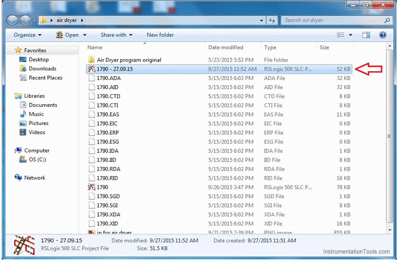
Step 2:

Double-click the backup program to open it.
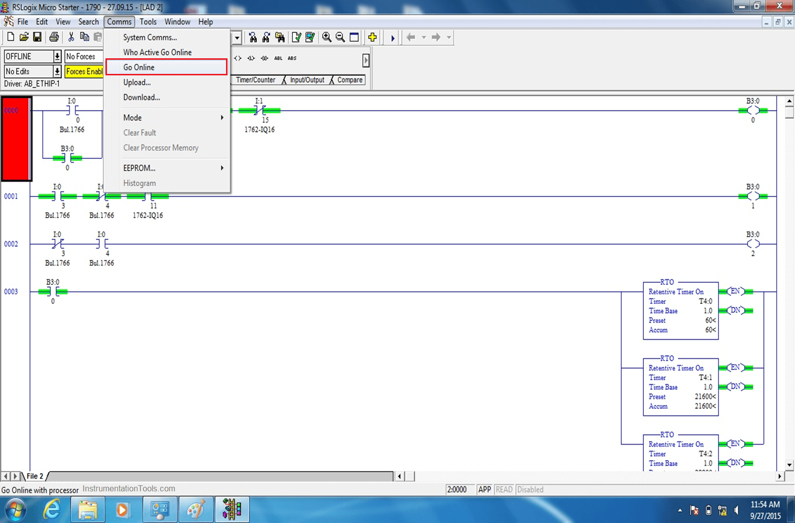
Procedure for connecting to Allen Bradley RS Logix 500 PLC

Step 3:

Then go to the “Comms” menu and select “Go Online”.

Go Online in RS Logix 500 PLC

Step 4:

If communication is established, the flag will be rotating as shown in the figure.
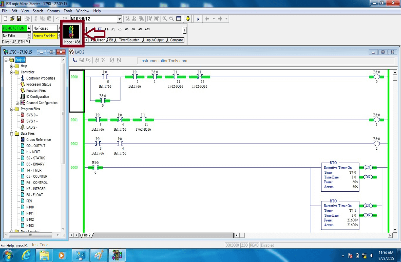
Allen Bradley PLC communication is established

Step 5:

Now the PLC program is online, do your activities like testing, troubleshooting, checking the I/O’s status, the configuration of a new instrument, etc.

Step 6:

After completion of your work with the PLC program, we have to take a fresh plc project backup.

Go to “File” and select “Save as” and specify the path to take backup of the PLC program.
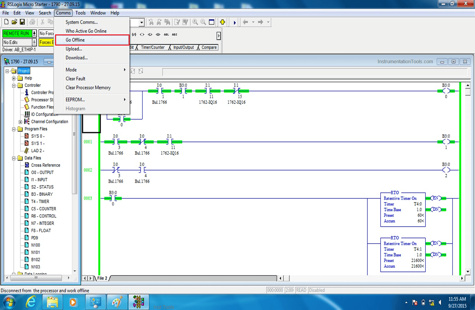
Step 6:

Go to the “Comms” menu and select “Go Offline”.
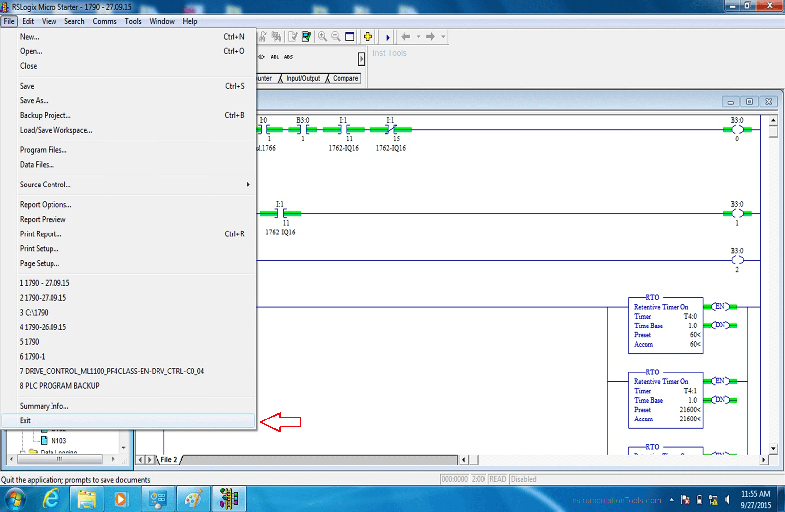
Go Offline in Allen Bradley PLC Software

Step 7:

Go to the “File” menu and select “Exit” to close the application.

Exit the PLC Software

Credits: PLQP Instrumentation Team

If you liked this article, then please subscribe to our YouTube Channel for Instrumentation, Electrical, PLC, and SCADA video tutorials.

You can also follow us on Facebook and Twitter to receive daily updates.

Read Next:

  • Connect to the Siemens S7 PLC
  • Difference Between Industrial Computer and PC
  • Troubleshoot Allen Bradley PLC Logic
  • Communication between InTouch Scada and Allen Bradley PLC
  • ON Delay Timer using PLC
Don't Miss Our Updates
Be the first to get exclusive content straight to your email.
We promise not to spam you. You can unsubscribe at any time.
Invalid email address
You've successfully subscribed !

Continue Reading

Normally-open and Normally-closed Switch Contacts
SCADA for Substation Automation
Basic Pumping System Application Used in Industrial Automation
Glass Cutting and Polishing Machine: PLC Automation Solution
Oil and Water Separation Process using PLC Programming
Pulse Generation using Timer in Siemens PLC
Share This Article
Facebook Whatsapp Whatsapp LinkedIn Copy Link
Share
Leave a Comment

Leave a Reply Cancel reply

Your email address will not be published. Required fields are marked *

Stay Connected

128.3kFollowersLike
69.1kFollowersFollow
208kSubscribersSubscribe
38kFollowersFollow

Categories

Explore More

Siemens Tia Portal PLC Training Course
Example of Controlling the PLC Output using Push Buttons
How to Design an Effective HMI? – Human Machine Interface
Can a PLC Function Without an HMI or SCADA?
What is a Control Panel and its types?
PLC Timer Programming Examples – TON, TOF, TP and TONR
#9 PLC Best Practices – Validate indirections
PLC based Metro Automation Project

Keep Learning

How to Use Symbol Factory Software for Graphic Design in HMI or SCADA

How to Use Symbol Factory Software for Graphic Design in HMI or SCADA?

Introduction to SCADA

Allen Bradley SLC 500 PLC Programming

PLC Program Paint Spraying

PLC Program for Paint Spraying

Trolley and hoist PLC control

PLC Crane Movement Control with Limit Switches

Power Supply Sizing for Industrial Automation Systems

Power Supply Sizing for Industrial Automation Systems

PLC Program to Operate Stamping of Parts

PLC Application for Stamping Operation – Example Programming

What is an Electromechanical Relay

Difference Between Solid State Relay and Electromechanical Relay

Learn More

process gas chromatographs

Multi Column Gas Chromatograph

What is a Current Transformer

What is a Current Transformer?

Instrumentation Word Game

Instrumentation Word Game

HMI book

HMI Handbook

RFID Based Projects for Engineering Students

RFID Projects for Engineering Students

Cable Tray Routing

Cable Routing

Optimal Control Systems

Parameter Optimization

Gate Valve Parts

What is Gate Valve ?

Follow US
All rights reserved. Reproduction in whole or in part without written permission is prohibited.
Welcome Back!

Sign in to your account

Username or Email Address
Password

Lost your password?