This is the PLC Program for Automatic Lamp Control in Godown (Storage Facility).
Automatic Lamp Control
Problem Description
In the old process, when the person enters the godown (Storage facility), he/she pressed the switch and all lamps in the godown will be ON. If we turn on all lamps together then more energy consumption occurs.
This problem occurs in the old process, so solutions are required for this process. We can solve this problem using simple automation or an interlock system.
Problem Diagram

PLC Problem Solution
We can solve this problem by simple interlock using PLC. As shown in the figure, consider one godown (storage facility) for industry and there are a couple of segments in the facility.
For example, we have considered only three segments for the storage facility. Say here we have 3 lamps for 3 segments and 3 switches for operation.
When a Person enters the godown (storage facility) for some work, he will operate lamp 1 by pressing switch 1. When work is completed then operator will turn OFF the light.
Here we will provide an interlocking system so a person cannot operate another segment’s lamp until he stops the first segment lamp. The same case occurs in other segments.
So by using this automation/interlock circuit, we can save energy.
Note: This type of interlock applies only to some types of storage facilities as these are operated by working in one segment at a time only before going to the next segment in the storage facility.
List of inputs/outputs
Digital Inputs
- SW1: I0.0
- SW2: I0.2
- SW3: I0.3
Digital Outputs
- Lamp 1: Q0.0
- Lamp 2: Q0.1
- Lamp 3: Q0.2
PLC Ladder diagram for Automatic lamp ON/OFF

PLC Program Description
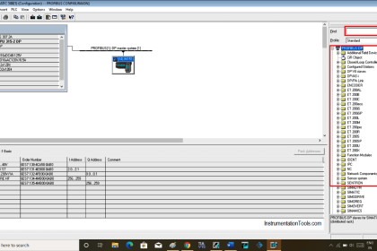
For this application, we used S7-1200 PLC and TIA portal software for programming.
Network 1:
In the above program, we have taken NO contact of SW 1(I0.0) for operating the Lamp 1 (Q0.0) and given NC contacts in series. so when the user press other switches, Lamp 1(Q0.0) will be OFF.
Network 2:
In network 2, we have written logic for Lamp 2(Q0.1). By operating SW2 (I0.2) operator can operate Lamp 2(Q0.1). And given NC contacts in series, so when user press other switches, Lamp 2(Q0.1) will be OFF.
Network 3:
In network 3, we have written logic for Lamp 3(Q0.2).By operating SW3 (I0.2) operate can operate Lamp 3(Q0.2). And given NC contacts in series, so when user press other switches, Lamp 3(Q0.2) will be OFF.
Runtime Test Cases

Note: The above PLC Logic provided for basic idea about application of PLC Program for Automatic Lamp Control. The Logic is limited and not complete application.
If you liked this article, then please subscribe to our YouTube Channel for PLC and SCADA video tutorials.
You can also follow us on Facebook and Twitter to receive daily updates.
Read Next: