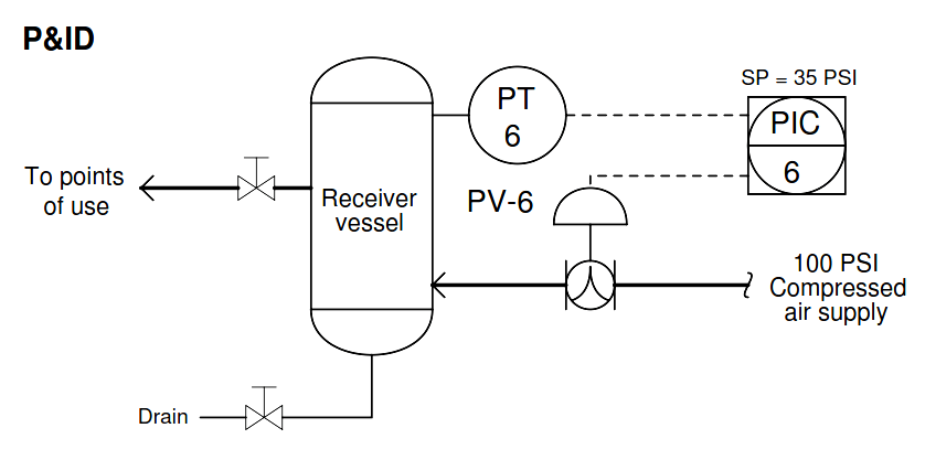
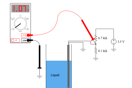
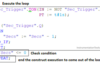
Determine whether or not the following pressure transmitter (PT) loop faults (considered individually) could account for this air pressure regulating system failing with zero pressure in the receiver vessel.
PT Loop Diagram
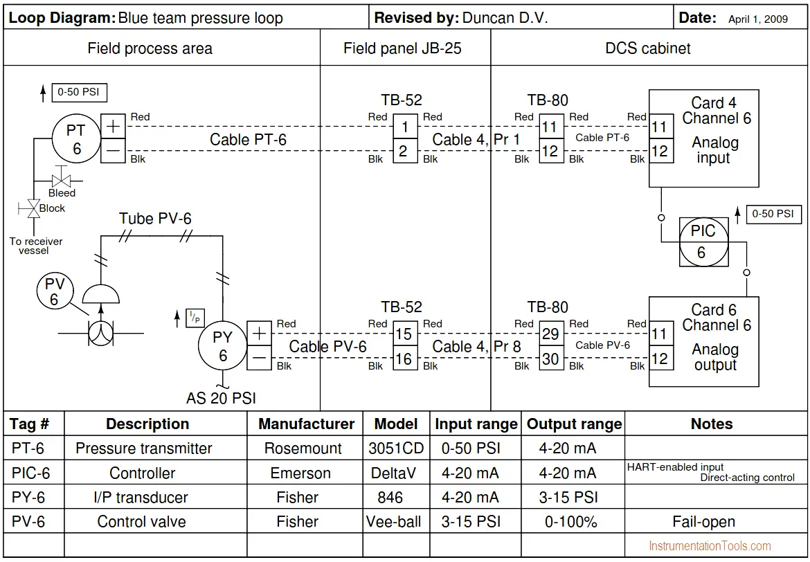
Answer either “yes” or “no” for each fault mentioned below:
- Receiver vessel drain valve left open
- Transmitter block valve shut and bleed valve open
- Transmitter block valve open and bleed valve shut
- PIC left in manual mode, 100% output (20 mA to I/P)
- Cable PV-6 severed (failed open) •
- I/P air supply shut off
- Short between TB-52, terminals 1 and 2
- Short between TB-52, terminals 15 and 16
- PT-6 miscalibrated, registering 5 PSI too high
- PY-6 output failed high (15 PSI)
Answer:
Receiver vessel drain valve left open – No
Transmitter block valve shut and bleed valve open – No
Transmitter block valve open and bleed valve shut – No
PIC left in manual mode, 100% output (20 mA to I/P) – Yes
Cable PV-6 severed (failed open) – No
I/P air supply shut off – No
Short between TB-52, terminals 1 and 2 – Yes
Short between TB-52, terminals 15 and 16 – No
PT-6 miscalibrated, registering 5 PSI too high – No
PY-6 output failed high (15 PSI) – Yes
Share your answers with us through the below comments section.
Read Next:
- PT Re-Range Question
- DP Pneumatic Transmitter
- DP Transmitter Problem
- Pressure Gauge Errors
- Calibration Lab Exercise
Credits: Tony R. Kuphaldt


Why is PT-6 miscalibrated, registering 5 PSI too high – No?
I thought that if PT-6 registers 5 PSI as high, so PIC-6 will close PV-6 to prevert further air coming.