Inst ToolsInst ToolsInst Tools
  • Courses
  • Automation
    • PLC
    • Control System
    • Safety System
    • Communication
    • Fire & Gas System
  • Instrumentation
    • Design
    • Pressure
    • Temperature
    • Flow
    • Level
    • Vibration
    • Analyzer
    • Control Valve
    • Switch
    • Calibration
    • Erection & Commissioning
  • Interview
    • Instrumentation
    • Electrical
    • Electronics
    • Practical
  • Q&A
    • Instrumentation
    • Control System
    • Electrical
    • Electronics
    • Analog Electronics
    • Digital Electronics
    • Power Electronics
    • Microprocessor
  • Request
Search
  • Books
  • Software
  • Projects
  • Process
  • Tools
  • Basics
  • Formula
  • Power Plant
  • Root Cause Analysis
  • Electrical Basics
  • Animation
  • Standards
  • 4-20 mA Course
  • Siemens PLC Course
Reading: Determine LRV and URV settings for the Level Transmitter
Share
Font ResizerAa
Inst ToolsInst Tools
Font ResizerAa
  • Courses
  • Design
  • PLC
  • Interview
  • Control System
Search
  • Courses
  • Automation
    • PLC
    • Control System
    • Safety System
    • Communication
    • Fire & Gas System
  • Instrumentation
    • Design
    • Pressure
    • Temperature
    • Flow
    • Level
    • Vibration
    • Analyzer
    • Control Valve
    • Switch
    • Calibration
    • Erection & Commissioning
  • Interview
    • Instrumentation
    • Electrical
    • Electronics
    • Practical
  • Q&A
    • Instrumentation
    • Control System
    • Electrical
    • Electronics
    • Analog Electronics
    • Digital Electronics
    • Power Electronics
    • Microprocessor
  • Request
Follow US
All rights reserved. Reproduction in whole or in part without written permission is prohibited.
Inst Tools > Blog > Practical Questions > Determine LRV and URV settings for the Level Transmitter

Determine LRV and URV settings for the Level Transmitter

Last updated: June 6, 2018 9:50 am
Editorial Staff
Practical Questions
1 Comment
Share
2 Min Read
SHARE

Determine LRV and URV settings for the Level Transmitter

Question :

Determine the LRV and URV settings for the water seal drum level transmitter (LT-21), assuming the LRV point is at the lower nozzle and the URV point is at the upper nozzle (the two nozzles being 3 feet 8 inches apart from each other), and that the remote seal fill fluid has a specific gravity of 0.934:
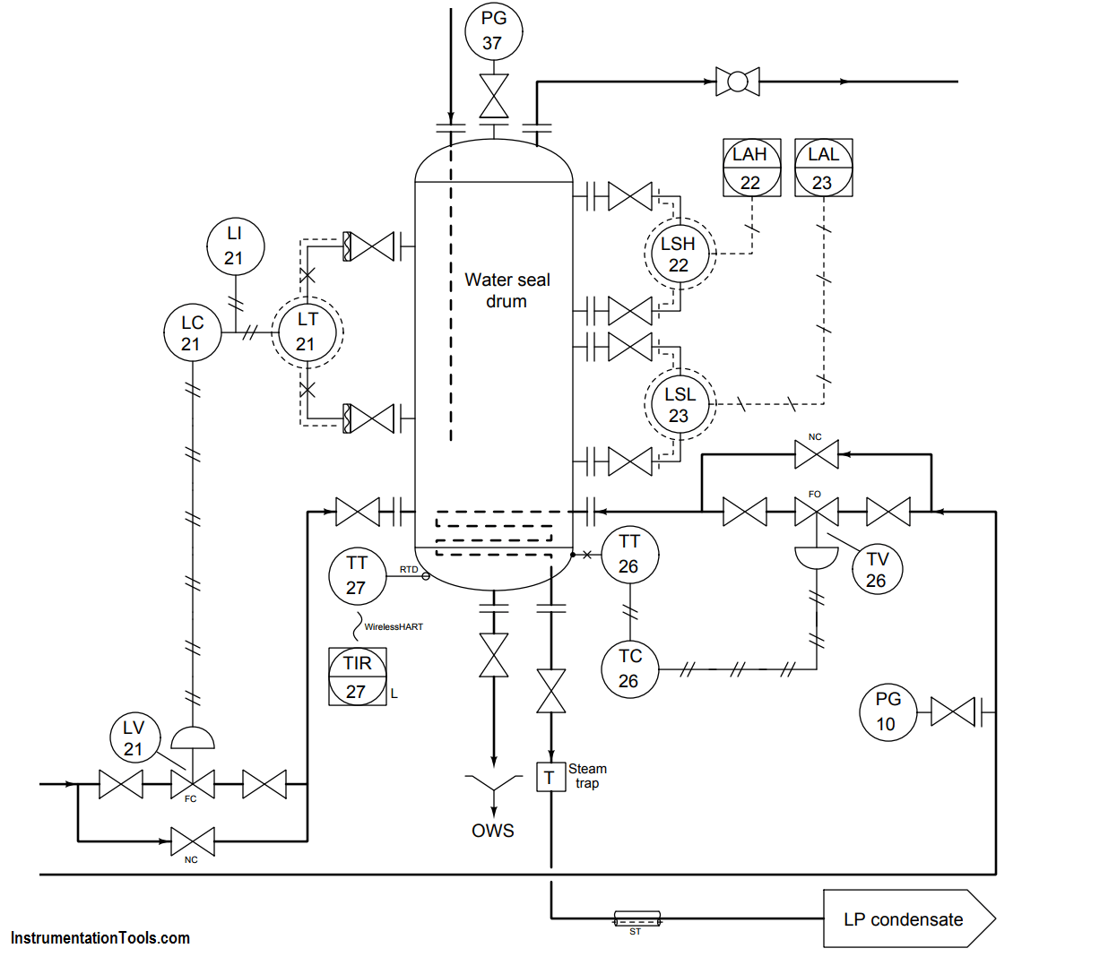
water seal drum lever transmitter

Answer :

The elevation for this transmitter (i.e. the total differential pressure applied by the height of fill fluid on both sides) is equal to the total height difference between the remote seal diaphragms multiplied by the specific gravity of the fill fluid:

Pelevation = (44 in)(0.934) = 41.1 ”WC

In the LRV condition, this is the only pressure seen by the transmitter. Therefore, 41.1 ”WC is the appropriate LRV setting for this transmitter. If we assume that the “H” port of this DP transmitter connects to the lower nozzle, the LRV will be -44.1 ”WC. If we assume the “H” port connects to the upper nozzle, the LRV will be +41.4 ”WC.

In the URV condition, we have the exact same amount of elevation (the fill fluid inside the capillary tubes) but on the lower nozzle we have the hydrostatic pressure of 44 vertical inches of water (i.e. the water inside the seal drum). Thus, in the URV condition the transmitter sees a differential pressure of:

Pdifferential = 44” WC − 41.1 ”WC = 2.9 ”WC

If we assume the “H” port of this DP transmitter connects to the lower nozzle, the URV will be +2.9 ”WC.

If we assume the “H” port of this DP transmitter connects to the upper nozzle, the URV will be -2.9 ”WC.
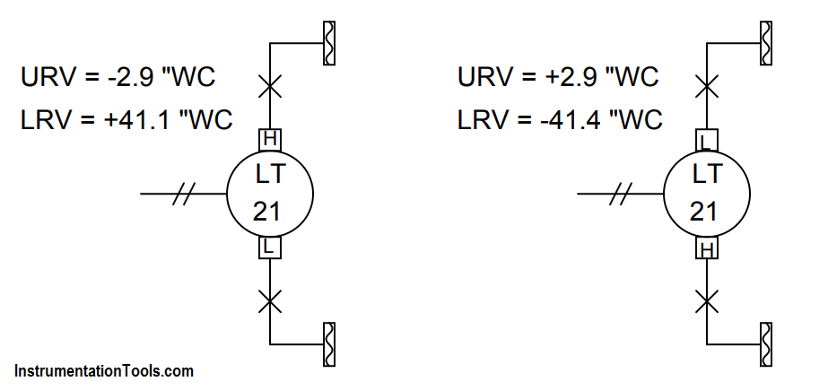
Differential Transmitter capillary tubes

Don't Miss Our Updates
Be the first to get exclusive content straight to your email.
We promise not to spam you. You can unsubscribe at any time.
Invalid email address
You've successfully subscribed !

Continue Reading

Signal Strength of Guided-wave Radar Level Instrument
Calculate Differential Pressure Sensed by Level Transmitter
Instrument Lab Exercise – Ranging and Manometer Usage
Liquid Flow Control Loop Controller Action
Programmable Logic Controller (PLC) Questions and Answers – 16
PT Loop Diagram Faults
Share This Article
Facebook Whatsapp Whatsapp LinkedIn Copy Link
Share
1 Comment
  • N M P KUMAR UPPULURI says:
    April 13, 2018 at 9:10 am

    This is a very helpful information. It would be help full if you specify how to make a head correction for Level transmitters.

    Reply

Leave a Reply Cancel reply

Your email address will not be published. Required fields are marked *

Stay Connected

128.3kFollowersLike
69.1kFollowersFollow
210kSubscribersSubscribe
38kFollowersFollow

Categories

Explore More

Calculate the Thermocouple Output millivolts
Problem on Weigh feeder
DP Transmitter Error Calculations
Programmable Logic Controller (PLC) Questions and Answers – 13
Draw Limit Switch Symbol ?
Troubleshooting PLC Permissive Inputs
Determine Resistance value of Resistors
Programmable Logic Controller (PLC) Questions and Answers – 7

Keep Learning

Calculate the Thermocouple’s Measurement Junction Temperature

Calculate the Thermocouple’s Measurement Junction Temperature

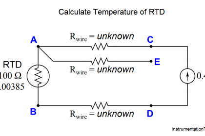
Calculate Temperature of Three Wire RTD

Determine the Temperature of 3 Wire RTD

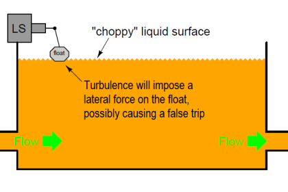
Float-type Level Switch for Sensing Low Oil Level

Float-type Level Switch for Sensing Low Oil Level

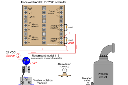
Loop Powered Pressure Transmitter

Loop Powered Pressure Transmitter

Which instrument is at fault in this system

Which Instrument is at Fault in this System?

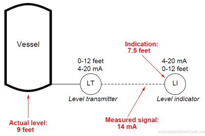
Transmitter Calibration Range of a Vessel Level

Transmitter Calibration Range of a Vessel Level

pressure transmitter calibration setup

Why Pressure Vessel Connected to Tubing System?

PLC program to control a water pump

PLC Program to Control a Water Pump

Learn More

Power Systems Questions & Answers

Power Systems MCQ Series 8

Barometer Principle

What is a Barometer?

Cars Garage Counter From the Same Door PLC Logic

Cars Garage Counter From the Same Door PLC Logic

PLC Batch System for 4 Tanks Mixing using CX-Programmer

PLC Batch System for 4 Tanks Mixing using CX-Programmer

knock-out drum

Applying Probability Laws to a Safety Instrumented System

What is a Magnetic Contactor

What is a Magnetic Contactor? – Principle, Types, Advantages

Reliability of a Control System

Reliability of a Control System

Software Testing Projects

Software Testing Projects – How to Approach the Process Effectively?

Menu

  • About
  • Privacy Policy
  • Copyright

Quick Links

  • Learn PLC
  • Helping Hand
  • Part Time Job

YouTube Subscribe

Follow US
All rights reserved. Reproduction in whole or in part without written permission is prohibited.
Welcome Back!

Sign in to your account

Username or Email Address
Password

Lost your password?