Inst ToolsInst ToolsInst Tools
  • Courses
  • Automation
    • PLC
    • Control System
    • Safety System
    • Communication
    • Fire & Gas System
  • Instrumentation
    • Design
    • Pressure
    • Temperature
    • Flow
    • Level
    • Vibration
    • Analyzer
    • Control Valve
    • Switch
    • Calibration
    • Erection & Commissioning
  • Interview
    • Instrumentation
    • Electrical
    • Electronics
    • Practical
  • Q&A
    • Instrumentation
    • Control System
    • Electrical
    • Electronics
    • Analog Electronics
    • Digital Electronics
    • Power Electronics
    • Microprocessor
  • Request
Search
  • Books
  • Software
  • Projects
  • Process
  • Tools
  • Basics
  • Formula
  • Power Plant
  • Root Cause Analysis
  • Electrical Basics
  • Animation
  • Standards
  • 4-20 mA Course
  • Siemens PLC Course
Reading: Simulate Different Values for Pressure Instrument Under Test
Share
Font ResizerAa
Inst ToolsInst Tools
Font ResizerAa
  • Courses
  • Design
  • PLC
  • Interview
  • Control System
Search
  • Courses
  • Automation
    • PLC
    • Control System
    • Safety System
    • Communication
    • Fire & Gas System
  • Instrumentation
    • Design
    • Pressure
    • Temperature
    • Flow
    • Level
    • Vibration
    • Analyzer
    • Control Valve
    • Switch
    • Calibration
    • Erection & Commissioning
  • Interview
    • Instrumentation
    • Electrical
    • Electronics
    • Practical
  • Q&A
    • Instrumentation
    • Control System
    • Electrical
    • Electronics
    • Analog Electronics
    • Digital Electronics
    • Power Electronics
    • Microprocessor
  • Request
Follow US
All rights reserved. Reproduction in whole or in part without written permission is prohibited.
Inst Tools > Blog > Practical Questions > Simulate Different Values for Pressure Instrument Under Test

Simulate Different Values for Pressure Instrument Under Test

Last updated: June 3, 2020 12:10 pm
Editorial Staff
Practical Questions
No Comments
Share
2 Min Read
SHARE

One challenge technicians face when calibrating low-pressure instruments is how to generate very low air pressures to simulate different low-pressure conditions for the pressure instrument under test. Measuring low pressures is no problem at all: very simple manometers (or gauges) will do the job quite nicely.

Most mechanical air compressors, however, generate pressures far exceeding the range of most manometers. Though it is possible to purchase precision pressure regulators for reducing such large pressures down to a level measurable by a manometer, these devices are expensive.

Also Read: Pressure Gauge Testing

A simple way to “divide” the pressure output of a standard pressure regulator from a few PSI to a few inches of water is to use a pair of small valves (preferably needle valves allowing for precise adjustment) to throttle the flow of compressed air and vent the regulator’s output to atmosphere, then tap between those valves to obtain a reduced pressure:

calibrating low-pressure instrument


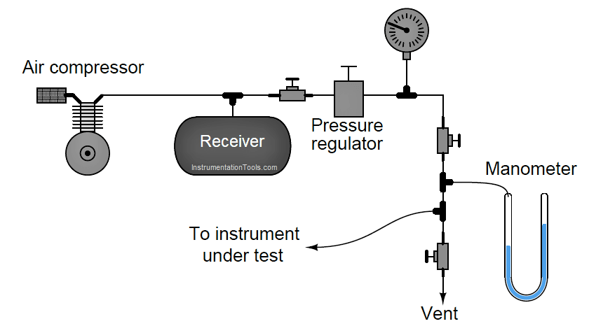
Draw an equivalent schematic diagram showing an electrical model for this pneumatic system, and then explain how it works:

electrical model for this pneumatic system

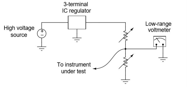
Share your explanation for the above equivalent circuit.

Questions for You:

1. Explain what you could do with one or both of the two needle valves to increase the amount of pressure sent to the instrument under test.

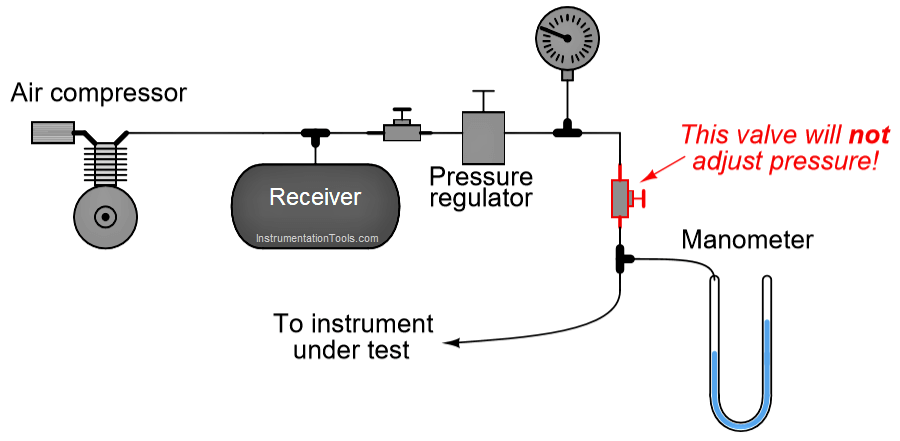
2. Explain why placing a valve in “series” with the regulator’s output will not adjust pressure to the instrument under test or the manometer.

needle valve for precise adjustment


Share your answers with us through below comments section.

Read Next:

  • What is Needle Valve
  • Series-Parallel Resistor Circuit
  • Questions on Control Valves
  • Instrument Air Manifold
  • Air Pressure Inside the Tank

Credits: Tony Kuphaldt

Don't Miss Our Updates
Be the first to get exclusive content straight to your email.
We promise not to spam you. You can unsubscribe at any time.
Invalid email address
You've successfully subscribed !

Continue Reading

PLC Permissive for Motor Control
Draw the appropriate Pressure Switch Symbol ?
Pneumatic Level Transmitter Calibration Table
Process Control High Level Alarm Fault Analysis
DP Transmitter Problem
Hydrostatic Pressure Measurement Questions
Share This Article
Facebook Whatsapp Whatsapp LinkedIn Copy Link
Share
Leave a Comment

Leave a Reply Cancel reply

Your email address will not be published. Required fields are marked *

Stay Connected

128.3kFollowersLike
69.1kFollowersFollow
210kSubscribersSubscribe
38kFollowersFollow

Categories

Explore More

Calculate LRV and URV for 4-20 mA Loop-powered DP Transmitter
Solenoid Valves Practical Problems
10 Questions on Reforming Furnace Control System
Programmable Logic Controller (PLC) Questions and Answers – 5
Differential Capacitance Pressure Sensor Circuit
Identify Two Pressure Switches Logic
PLC connected to Three Pushbutton Switches
How to Draw a Schematic Diagram ?

Keep Learning

Manometer Measures Differential Pressure

How Manometer Measures Differential Pressure for Different Fluids?

Level-Measuring-Instruments-Velocities-of-Propagation

Level Measuring Instruments Velocities of Propagation

Span of Pressure Gauge

How to Decrease Span of Pressure Gauge?

Pneumatic Moment-balance Differential Pressure Transmitter

Pneumatic Moment-balance Differential Pressure Transmitter

Calibration setup for a low-range electronic pressure transmitter

Instrument Lab Exercise – Ranging and Manometer Usage

pressure switches relay circuit

Determine the functions of Pressure Switches ?

Calculate the Thermocouple Output millivolts

Calculate the Thermocouple Output millivolts

Dry Leg

Calculate 0%, 50%, and 100% Calibration Points for ΔP transmitter

Learn More

Sensors Objective Questions

Sensors Objective Questions

RTD Measuring with three leads

How 3 Wire RTD Lead Wire Resistance Eliminated?

Example of feedback principle

Example of Feedback System

Safety Instrumented System SIS Component Selection

SIS Component Selection – Safety Instrumented System

Conductive Level Switch Principle

Conductive Level Switch Principle

Hazard Identification and Risk Assessment

Hazard Identification & Risk Assessment (HIRA)

Simple PLC example Hardware configurations

Muting Functions of Safety Control Circuits – PLC Example

Power Electronics objective questions and answers

Top 50 Power Electronics Quiz

Menu

  • About
  • Privacy Policy
  • Copyright

Quick Links

  • Learn PLC
  • Helping Hand
  • Part Time Job

YouTube Subscribe

Follow US
All rights reserved. Reproduction in whole or in part without written permission is prohibited.
Welcome Back!

Sign in to your account

Username or Email Address
Password

Lost your password?