Inst ToolsInst ToolsInst Tools
  • Courses
  • Automation
    • PLC
    • Control System
    • Safety System
    • Communication
    • Fire & Gas System
  • Instrumentation
    • Design
    • Pressure
    • Temperature
    • Flow
    • Level
    • Vibration
    • Analyzer
    • Control Valve
    • Switch
    • Calibration
    • Erection & Commissioning
  • Interview
    • Instrumentation
    • Electrical
    • Electronics
    • Practical
  • Q&A
    • Instrumentation
    • Control System
    • Electrical
    • Electronics
    • Analog Electronics
    • Digital Electronics
    • Power Electronics
    • Microprocessor
  • Request
Search
  • Books
  • Software
  • Projects
  • Process
  • Tools
  • Basics
  • Formula
  • Power Plant
  • Root Cause Analysis
  • Electrical Basics
  • Animation
  • Standards
  • 4-20 mA Course
  • Siemens PLC Course
Reading: What is Poppet Valve? When we Use a Poppet Valve?
Share
Font ResizerAa
Inst ToolsInst Tools
Font ResizerAa
  • Courses
  • Design
  • PLC
  • Interview
  • Control System
Search
  • Courses
  • Automation
    • PLC
    • Control System
    • Safety System
    • Communication
    • Fire & Gas System
  • Instrumentation
    • Design
    • Pressure
    • Temperature
    • Flow
    • Level
    • Vibration
    • Analyzer
    • Control Valve
    • Switch
    • Calibration
    • Erection & Commissioning
  • Interview
    • Instrumentation
    • Electrical
    • Electronics
    • Practical
  • Q&A
    • Instrumentation
    • Control System
    • Electrical
    • Electronics
    • Analog Electronics
    • Digital Electronics
    • Power Electronics
    • Microprocessor
  • Request
Follow US
All rights reserved. Reproduction in whole or in part without written permission is prohibited.
Inst Tools > Blog > Control Valves > What is Poppet Valve? When we Use a Poppet Valve?

What is Poppet Valve? When we Use a Poppet Valve?

In the poppet valve, in which the poppet is piston shaped or ball-shaped that moves valve seat position open and close.

Last updated: October 17, 2023 2:01 pm
R Jagan Mohan Rao
Control Valves
No Comments
Share
5 Min Read
SHARE

Directional control valves control the flow direction, they vary significantly in physical characteristics and operation.

Contents
Poppet ValveConstruction and WorkingVarious Types of Poppet Valves2/2 Poppet Valve3/2 Poppet Valve4/2 Poppet VaveAdvantagesDisadvantages

One among them is the poppet valve, in which the poppet is piston shaped or ball-shaped that moves the valve seat position open and close (ON or OFF).

Directional control valves may be classified according to the method of actuating the valve element.

A poppet-type valve usually hydraulically operated.

Poppet Valve

Poppet Valve

The poppet could also be a ball or simple discs, cones similar item like a plate used in conjunction with simple valve seats to control flow. They are made to sit over a specially constructed, finely machined, and polished seat.   

Large capacity valves need large valve seat areas, resulting in large operating force.

The high pressure in hydraulic systems thus tends to present the use of simple poppet valves and they are, therefore, predominantly found in the low-pressure pneumatic systems.

Construction and Working

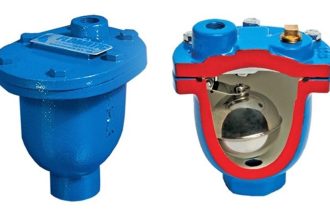
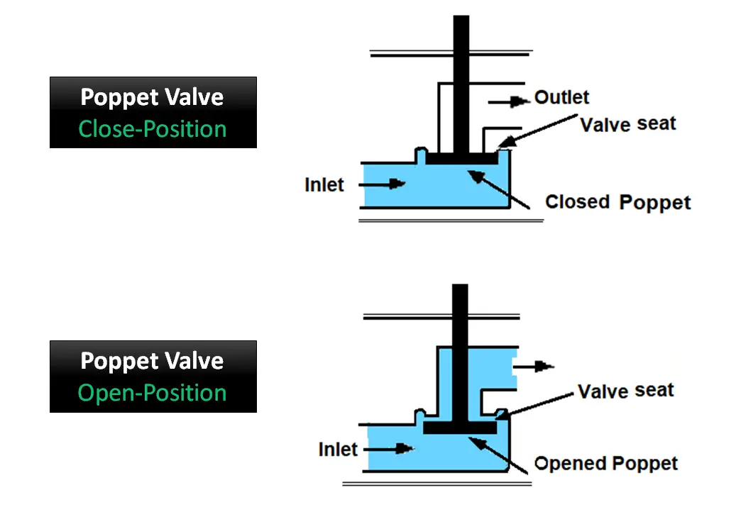
The above figure shows the simplified poppet valve. The basic construction of a poppet valve comprises a movable poppet that closes against a valve seat. Pressure from the inlet serves to hold the valve tightly closed.

A little force is required to the poppet stem that opens the poppet. The action is similar to the internal combustion of an automobile engine.

In certain applications, the poppet valves are operated by solenoids also, in which, poppet stem is actuated by energized solenoid coil.

The poppet stem usually has an O-ring seal, seated in a groove, and acts to stop fluid leakage. In some valves, the poppets are held in seated positions by springs. The number of poppets in a valve depends on the purpose of the valve used.

Thus the poppet valves have an intrinsic characteristic of fast response and they find application in control circuits.  

Various Types of Poppet Valves

The following are the different types of poppet valves

  • 2/2 Poppet Valve
  • 3/2 Poppet Valve
  • 4/2 Poppet Valve

2/2 Poppet Valve

The figure below shows the construction and symbol of a simple 2/2 normally closed valve.

2 Way Poppet Valve

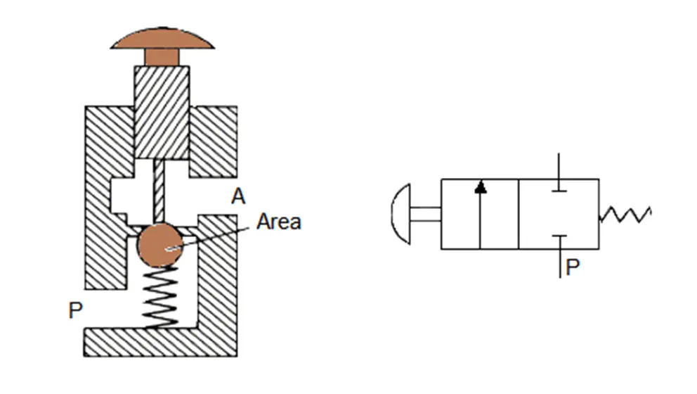
The release of the pushbutton lifts the ball off its seat and allows fluid to flow from port P to port A.

When the button is released, spring and fluid pressure force the ball upward again, closing the valve.

3/2 Poppet Valve

The figure below shows the construction and the symbol of a disc seal 3/2 poppet.

3 Way Poppet Valve

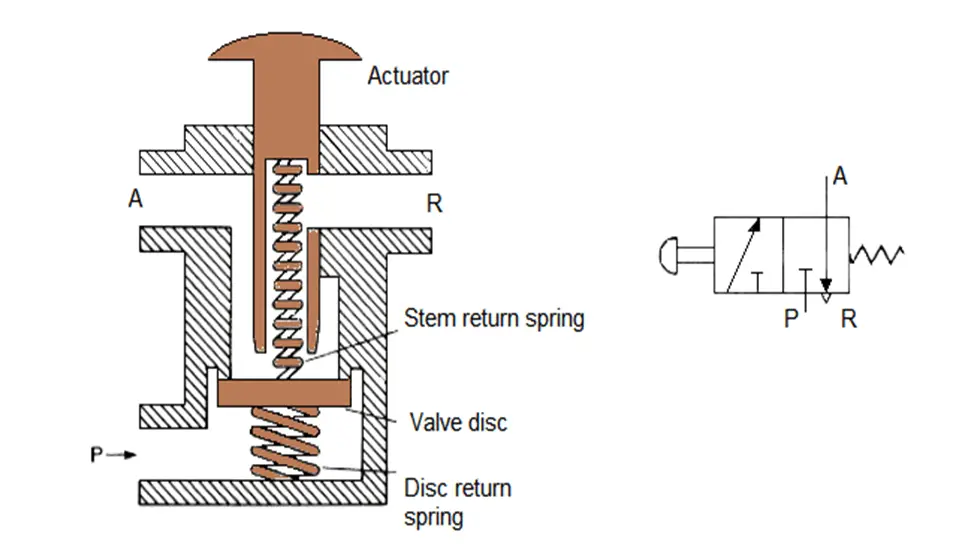
With the pushbutton released, ports A and R are first sealed, then the valve disc pushed downwards to open the valve and connect ports P and A.

Spring force and fluid pressure from port P close the valve.

4/2 Poppet Vave

The figure below is a poppet change over 4/2 valve using two stems and disc valves.

When the pushbutton released, A and R ports are linked via the hollow left-hand stem, and P and B ports are linked via the normally open right-hand disc valve.

4 Way Poppet Valve

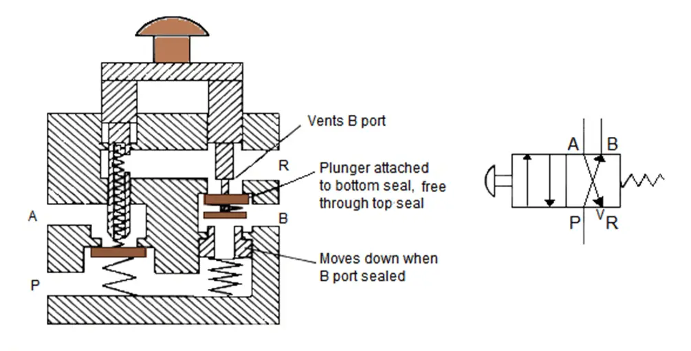
The moment when the pushbutton is pressed, the link between ports A and R is first closed, then the link between P and B closed.

The link between A and P is next opened, and finally, the link between B and R ports is opened. When the pushbutton is released, fluid and spring pressure put the valve back to its original state.

Advantages

  • The manufacturing cost of the poppet-valve system is economical when compared to the other types.
  • It can give larger values of valve-flow area to piston area than most the other types.
  • The poppet valves are simple, inexpensive, and insensitive to dirt.
  • They also have an extended working life as they have few parts which are subjected to wear and tear.

Disadvantages

  • The main disadvantage of these valves is the high actuating force required to operate them.
  • This high actuating force is required to overcome both the force of the built-in reset spring as well as the force exerted by the compressed air.

Reference: Hydraulics and Pneumatics, Technician’s and Engineer’s book handbook by Andrew Parr.

If you liked this article, then please subscribe to our YouTube Channel for Instrumentation, Electrical, PLC, and SCADA video tutorials.

You can also follow us on Facebook and Twitter to receive daily updates.

Read Next:

  • Valve Commissioning
  • What is a Pilot Valve?
  • Types of Spool Valves
  • What is an Unloading Valve?
  • Types of Isolation Valves
Don't Miss Our Updates
Be the first to get exclusive content straight to your email.
We promise not to spam you. You can unsubscribe at any time.
Invalid email address
You've successfully subscribed !

Continue Reading

Snap Acting Relay Working Principle
What is Swing Check Valve ?
Trip Valve Principle
Current to Pressure (I/P) Converter Principle
Refrigeration Compressor Turbine Not-tripping when needed Trip
Control Valve Flow Direction
Share This Article
Facebook Whatsapp Whatsapp LinkedIn Copy Link
Share
Leave a Comment

Leave a Reply Cancel reply

Your email address will not be published. Required fields are marked *

Stay Connected

128.3kFollowersLike
69.1kFollowersFollow
210kSubscribersSubscribe
38kFollowersFollow

Categories

Explore More

Instrumentation Inspection Report
Solenoid Valve Selection Criteria
What is a Pneumatic Cylinder?
Complementary Control Valve Sequence
Electro Pneumatic Valve Positioner Schematic & Principle
Pilot-operated Relief Valve Principle
Valve Safety Factor
What is a 3-way Solenoid Valve ?

Keep Learning

Pressure Control Valve

What is Pressure Control Valve?

Valve Glossary

Valve Terminology Glossary

Globe Valve Parts

What is Globe Valve ?

Chocked flow

Control Valve Cavitation and Flashing

Shut down valve

What is Shutdown Valve?

Two SOV Connections

Two Solenoid Valves Working Principle

Triple-offset Butterfly Valves

Butterfly Valves – Concentric, Double-offset, and Triple-offset

Volume Booster Working Principle

Control Valve Volume Booster Working Principle

Learn More

Digital Electronics Multiple Choice Questions

Programmable Logic Array Objective Questions

PLC Program for Positive edge pulse output for one scan cycle

PLC Program for Positive Edge Pulse Output for One Scan Cycle

Battery Hazard

Battery Hazards

How to Install Thermowell on an Elbow?

Difference Between Adhesion and Cohesion

Difference Between Adhesion and Cohesion

PLC automation timers and counters

Medium-Level PLC Exercise for Students in Automation

HMI configuration for Delta VFD

Modbus Communication between Delta PLC with VFD

Electronics Mini Projects

300+ Best Electronics Mini Projects

Menu

  • About
  • Privacy Policy
  • Copyright

Quick Links

  • Learn PLC
  • Helping Hand
  • Part Time Job

YouTube Subscribe

Follow US
All rights reserved. Reproduction in whole or in part without written permission is prohibited.
Welcome Back!

Sign in to your account

Username or Email Address
Password

Lost your password?