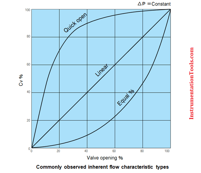
Each valve has a flow characteristic, which describes the relationship between the flow rate and valve travel.
As a valve opens, the flow characteristic, which is inherent to the design of the selected valve, allows a certain amount of flow through the valve at a particular percentage of the stroke. This enables flow regulation through the valve in a predictable manner.
The three most common types of flow characteristics are:
- Linear
- Equal percentage
- Quick opening
Linear valve characteristics:
This characteristic provides a linear relationship between the valve position and the flowrate. The flow through a linear valve varies directly with the position of the valve stem.
This flow- travel relationship, if plotted on rectilinear coordinates, approximates a straight line, thereby giving equal volume changes for equal lift changes regardless of percent of valve opening.
These valves are often used for liquid level control and certain flow control operations requiring constant gain.
Equal percentage valve characteristics:
The equal percentage valve plug produces the same percentage change in flow per fixed increment of valve stroke at any location on its characteristic curve.
For example, if 30% stem lift produces 5 gpm and a lift increase of 10% to 40% produces 8 gpm or a 60% increase over the previous 5 gpm, then a further stroke of 10% now produces a 60% increase over the previous 8 gpm for a total flow of 12.8 gpm.
These types of valves are commonly used for pressure control applications and are most suitable for applications where a high variation in pressure drop is expected.
Quick opening valve characteristics:
A quick opening valve plug produces a large increase in flow for a small initial change in stem travel. Near maximum flow is reached at a relatively low percentage of maximum stem lift.
Quick opening plugs are normally utilized in two position “On-Off” applications but may be used in some linear valve applications. This is possible because of its initial linear characteristic at a low percentage of stem travel.
The slope of this linear region is very steep which produces a higher initial gain than the linear plug but also increases the potential instability of the control valve.
Inherent valve characteristics:
An inherent flow characteristic is the relation between valve opening and flow under constant pressure conditions.
The inherent characteristic of a valve is obtained when there is a constant pressure drop across the valve for all valve positions; the process fluid is not flashing, cavitating or approaching sonic velocity (choked flow); and the actuator is linear (valve stem travel is proportional to the controller output).
Some valves have inherent characteristics that cannot be changed, such as full port ball valves and butterfly valves. For other valve types, such as the globe type, the inherent characteristics can be changed to suit the application.
Installed flow characteristic:
When valves are installed with pumps, piping and fittings, and other process equipment, the pressure drop across the valve will vary as the valve travel changes.
When the actual flow in a system is plotted against valve opening, the curve is called the installed flow characteristic and it will differ from the inherent valve characteristic which assumed constant pressure drop across the valve. When in service, a linear valve will in general resemble a quick opening valve while an equal percentage valve will in general resemble a linear valve.
Difference between installed and inherent characteristics:
The inherent flow characteristics do not reflect the actual performance of the valve as installed. The ideal condition of constant valve pressure drop (∆P) is unlikely to be true and the ‘operating’ characteristics will have deviation from the inherent characteristics and is termed the “Installed Flow Characteristics”.
The deviation in the characteristics depends on the pressure drop variation across the control valve, as the control valve operates from minimum flow at its initial travel position to its maximum flow at its fully opened position.
The variations in pressure drop across the valve can be attributed to two basic causes:
- The pump characteristic which results in an increase in pump head as the flow is reduced; and
- The reduction in line losses as the flow is reduced, causing more and more of the pump head to appear across the valve.
In a pipeline carrying fluid, the dynamic system pressure (Ps) is made up of two components:
1) the pressure drop across the control valve (Pv) and 2) the pressure drop along the pipeline (PL), excluding any fixed static or elevation pressure head component. It is given by:
PS = Pv + PL
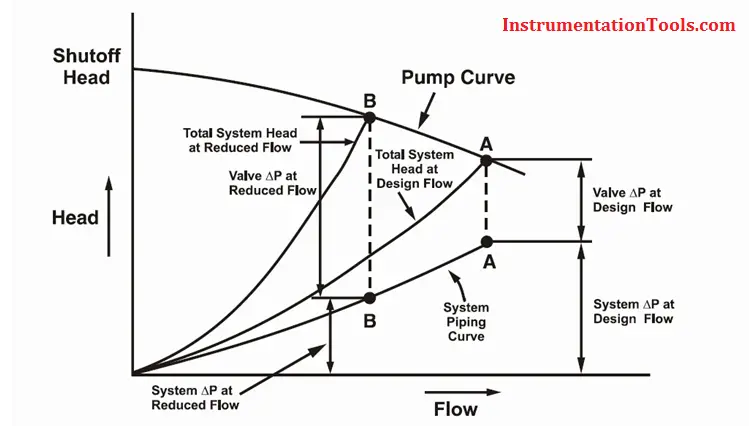
In the pump curve above, the point “A” is the point where the system resistance curve crosses the pump characteristic curve and indicates the operating conditions (flow and head). As the valve modulates to the closed position; the resistance to the system flow that the valve provides (valve pressure drop) will increase by shifting from point “A” towards point “B”. This increasing resistance will use more of the head in the system, as well as decrease system flow.
- Pressure drop across the control valve increases (∆Pv – ↑). The change in pressure drop across the valve can be attributed to two basic causes:
1) the pump characteristic, which results in an increase in pump head as the flow is reduced, and
2) the reduction in line losses as the flow is reduced, causing more and more of the pump head to appear across the valve. The amount that the pump head will increase with a decrease in system flow will depend upon the operating characteristics of the pump. A pump with a steep characteristic will produce a considerable increase in pressure head as the system resistance is increased. However, a flat characteristic pump will produce a relatively constant, high pressure head for any system flow. The relatively constant pressure would be preferable from a control standpoint.
- Pressure loss in the pipeline reduces (∆PL – ↓). This is because the decrease in system flow will result in a decrease in pressure drop along the pipeline and is proportional to the square root of the flow rate.
This indicates that the pressure drop across the valve in the system is not constant and it varies with flow and other changes in the system. This has a significant impact on the actual installed valve flow characteristic. The deviation from the inherent flow characteristic is a function of a property called Valve Authority. It is defined as the ratio of the full flow valve pressure drop to the system pressure drop (including the valve)
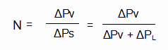
- N = Valve Authority
- ∆Pv = Pressure drop across the control valve
- ∆PL = Pressure drop due to pipeline friction losses
- ∆PS = System pressure drop = ∆Pv + ∆PL
When “N” approaches 1.0, then ∆PL is almost zero and ∆Pv approaches ∆Ps. This satisfies the requirement for the definition of valve inherent characteristics.
Distortion occurs when “N” falls from 1.0. This is the situation when the pipeline system pressure drop (∆Ps) is not concentrated at the control valve alone but well distributed along the pipeline. An inherently equal % characteristics control valve operating under such condition will behave like a linear valve and an inherently linear characteristics control valve will behave like a quick-opening control valve.
The effect of these system variables can be minimized by keeping the relative change in valve pressure drop as small as possible.
When the total flow is low, control valve pressure drop tends to be large fraction of the total system pressure loss; but at high flows this may not be true. A good design will respond well over the full range of conditions, hence it is important to pick the right characteristic for your system and size the valve for the right amount of pressure drop.
For good control, it is nice to take a fairly large pressure drop across a control valve. This way it will have a big influence on the total system, making the operators and control engineers happy. However, design engineers will worry that increasing pressure drop will tend to increase pumping and other operating costs. Compromise is necessary.
As a rule of thumb, design the system and size the valve so that 25 to 33% (1/3rd) of the total system pressure drop (including the valve) is taken across the control valve, with a minimum of 10-15 psig.
General rules:
How do you decide which valve control to use? Here are some rules of thumb:
Linear Characteristics:
- Used in liquid level or flow loops.
- Used in systems where the pressure drop across the valve is expected to remain fairly constant (i.e. steady state systems).
- Used when the pressure drop across the valve is a large proportion of the total pressure drop.
Equal Percentage Characteristics:
- Used in processes where large changes in pressure drop are expected.
- Used in processes where a small percentage of the total pressure drop is permitted by the valve.
- Used in temperature and pressure control loops.
Quick Opening Characteristics:
- Used for frequent on-off service.
- Used for processes where “instantly” large flow is needed (i.e. safety systems or cooling water systems).
Two rules of thumb for choosing the right flow characteristic:
- If most of the pressure drop is taken through the valve and the upstream pressure is constant, a linear characteristic will provide better control.
- If the piping and downstream equipment cause significant resistance to the system, equal percentage will provide better control.
Typical applications
General applications of of quick opening, linear and equal percentage valves are :
i) Quick opening valve:
a) Frequent on-off service.
b) Used for systems where ‘instant’ large flow is needed (safety or cooling water systems).
ii) Linear valve:
a) Liquid level and flow control loops.
b) Used in systems where the pressure drop across the valve is expected to remain fairly constant.
iii) Equal percentage valve (most commonly used in valves):
a) Temperature and pressure control loops.
b) Used in systems where large changes in pressure drop across the valve are expected.


Regarding the equal percentage discussion…
“For example, if 30% stem lift produces 5 gpm and a lift increase of 10% to 40% produces 8 gpm or a 60% increase over the previous 5 gpm, then a further stroke of 10% now produces a 60% increase over the previous 8 gpm for a total flow of 12.8 gpm.”
The lift increase following the stem lift should read “30% to 40%”.
My comment is incorrect due to a misinterpretation of the original sentence. The sentence is correct as stated; my apologies.