In some process applications, it is important that the control valve be able to completely stop fluid flow when placed in the “closed” position. Although this may seem to be a fundamental requirement of any valve, it is not necessarily so.
Many control valves spend most of their operating lives in a partially-open state, rarely opening or closing fully. Additionally, some control valve designs are notorious for the inability to completely shut off (e.g. double-ported globe valves).
Given the common installation of manual “block” valves upstream and downstream of a control valve, there is usually a way to secure zero flow through a pipe even if a control valve is incapable of tight shut-off. For some applications, however, tight control valve shut-off is mandatory.
For this reason we have several classifications for control valves, rating them in their ability to fully shut off.
Valve Seat Leakage Test
Seat leakage tolerances are given roman numeral designations, as shown in this table:

The “bubble test” used for Class VI seat leakage is based on the leakage rate of air or nitrogen gas past the closed valve seat as measured by counting the rate of gas bubbles escaping a bubble tube submerged under water.
For a 6 inch valve, this maximum bubble rate is 27 bubbles per minute (or about 1 bubble every two seconds):

It is from this leakage test procedure that the term bubble-tight shut-off originates. Class VI shut-off is often achievable only through the use of “soft” seat materials such as Teflon rather than hard metal-to-metal contact between the valve plug and seat.
Of course, this method of achieving bubble-tight shut-off comes at the price of limited operating temperature range and the inability to withstand nuclear radiation exposure.
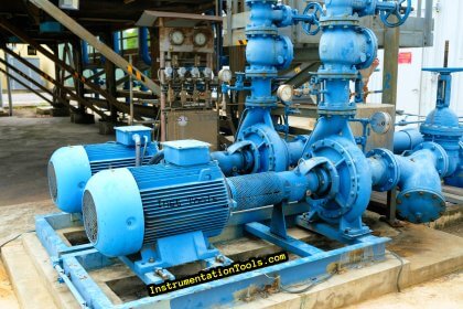
Special test fixtures are typically used in control valve rebuild shops to test the leakage rates of a rebuilt valve. One such test bench appears in this photograph:

In the foreground of this photograph we see a special “vise” used to make quick, pressure-tight connections to the flange of any control valve placed within it.
A movable flange sandwiches the control valve against a stationary flange, both flanges faced with high-density plastic for a pressure tight fit against the valve body flange faces.
A stainless-steel panel in the background provides a set of air pressure regulators, hand valves, rotameters, pressure gauges, and even a “bubble” flow indicator to measure leakage flow rate through the control valve under varying pressure conditions.


For control valve seat leakage, now as per new standard ANSI-FCI-70-2013, Class V valves can be tested through air also. If possible, please can you share this standard also on this website. Thanks,
Sir, can you give one example seat leakage calculation for class IV control valve CV 575