In certain specific applications, there is a need for completely unload pumps flow to the tank instead of relieving it over a relief valve. This can be done using unloading valves.
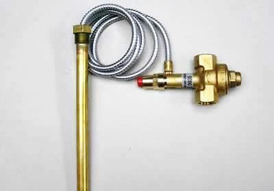
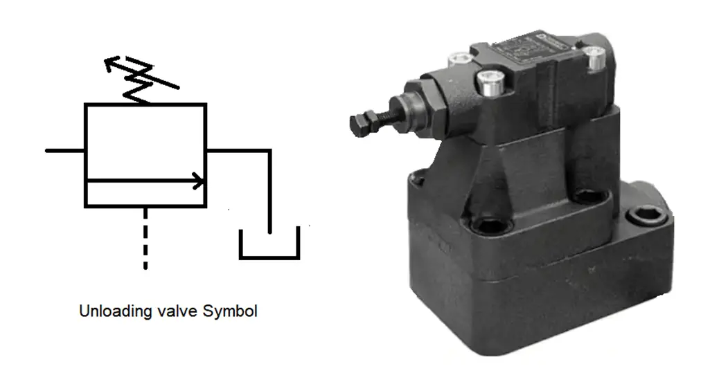
Unloading Valve
Let us imagine a case of a system, where there are two pumps. Both pumps are required to perform specific work.
After completion of the job, there is a need to maintain the required pressure in the system by operating only one pump and the delivery of the other pump must be sent to the tank at low pressure. This job is done by an unloading valve.
Principle
An unloading valve is a pressure control valve that works on the principle of the hydraulic force as opposed to a spring force.
When pressure builds to the point, where hydraulic force is greater than that of the spring force, then the valve spool is shifted.
Purpose
The unloading valves are used for relieving the extra pressure in a system, that is at low pressure and connecting it to the tank when the delivery of the pump is not used.
The unloading valve may be controlled by a special cock or a pilot valve.
Types of Unloading Valves
The unloading valves are classified into two types.
They are as follows.
- Direct operated pressure Unloading Valve
- Pilot operated pressure Unloading Valve
Direct Operated Unloading Valve
A direct-acting unloading valve consists of a spool held in the closed state by a spring.
The spool blocks flow from the inlet to the tank port under normal operating conditions.
High-pressure fluid from the pump exerts a force against the pilot as it enters from the external pilot port.
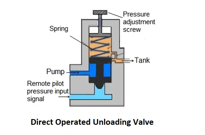
When the system pressure increases to the force of the spring setting the fluid bypasses the tank.
When the pressure goes above the spring setting, the spool opens fully to dump the surplus fluid into the tank at little or no pressure.
Pilot Operated Unloading Valve
Unloading spool is the addition in a pilot-operated unloading valve, it is not found in the pressure relief valve.
Without the unloading spool, this valve would function the same as any pilot-operated relief valve.
Pressure buildup within the pilot section would open a certain amount of fluid flow to the tank. It makes unbalances the poppet, allowing it to open and relieve excess pump flow to the tank.
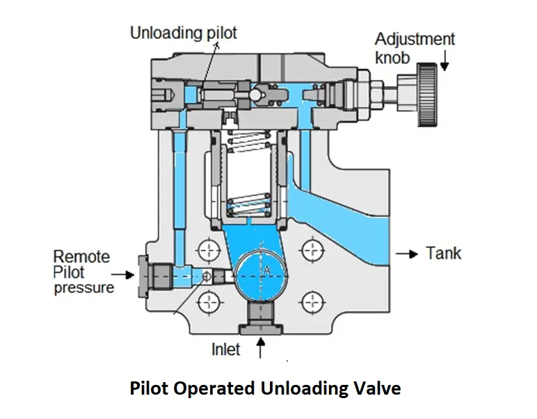
Unloading spool receives a signal through the remote-pilot port when the pressure in the working circuit goes more than its setting.
Simultaneously, fluid pressure on the spring-loaded ball in the pilot section starts to open it.
Pressure drop on the front side of the unloading spool brings down back force and pilot pressure from the high-pressure circuit forces the spring-loaded ball completely off its seat
Double Pumps with Unloading Valve
The primary use for an unloading valve is associated with a dual pump circuit. A high-pressure, low-flow pump along with a low-pressure, high-flow pump is used double pump operated circuit.
An un-loading valve is used with two pumps, create high discharge flow, and the other one able to create a high line pressure with low oil discharge.
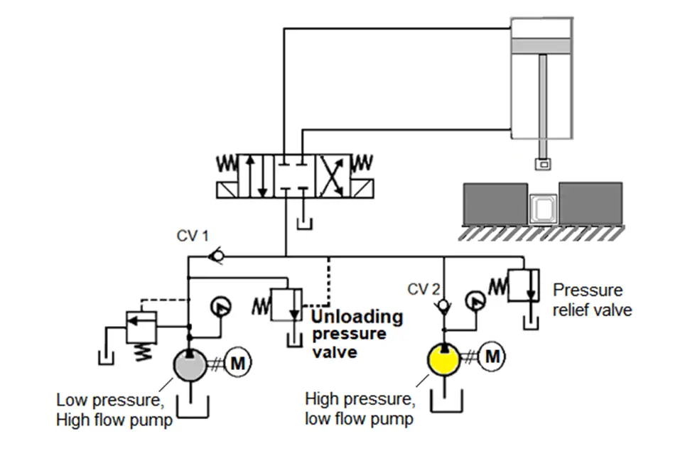
Deliveries of both pump are discharged into the circuit until the pressure approaches the setting of the unloading valve.
At this stage, fluid from the high pressure-low flow pump is passed through CV1 to the cylinder through the directional control valve but not allowed by CV2.
In a particular application, sheet metal punch press in which the hydraulic cylinder must extend rapidly over a length with low-pressure but high-flow requirements. This occurs under no load.
However during the punching operation for short motion, the pressure requirements are very high, but the flow requirements are low as the cylinder travel is small.
It eliminates the requirement of having a very expensive high-pressure, high-flow pump.
As and when the punching operation initiates, the increased pressure opens the unloading valve to unload the low-pressure pump.
The purpose of relief valve is to protect the high-pressure pump from high pressure buildup at the end of cylinder stoke and when the directional control valve (DCV) is in its spring-centered mode.
The check valve protects the low-pressure pump from high pressure due to the high-pressure pump, which occurs during punching operation, at the ends of the cylinder stroke, and when the directional control valve (DCV) is in its spring-centered mode.
Advantages
- The pressure of unloading valve is typically less of the relief valve.
- The oil getting hot can be avoided by re-circulation with second pump in circuit.
- Life span of O-rings can be extended by avoiding oil becoming hot.
- Less energy consumption.
Reference: Fluid Power Control Systems by MD Faiyaz Ahmed.
If you liked this article, then please subscribe to our YouTube Channel for Instrumentation, Electrical, PLC, and SCADA video tutorials.
You can also follow us on Facebook and Twitter to receive daily updates.
Read Next: