Regardless of valve type, all stem-actuated control valves require some form of seal allowing motion of the stem from some external device (an actuator ) while sealing process fluid so no leaks occur between the moving stem and the body of the valve. The general term for this sealing mechanism is packing.
This mechanical feature is not unlike the stuffing box used to seal seawater from entering a boat or ship at the point where the propeller shaft penetrates the hull:

The fundamental problem is the same for the ship as it is for the control valve: how to allow a moving shaft to pass through what needs to be an impenetrable barrier to some fluid (in the case of the ship’s hull, the fluid is seawater). The solution is to wrap the shaft in a flexible material that maintains a close fit to the shaft without binding its motion.
A traditional packing material for ship propeller shafts is flax rope. Some form of lubrication is usually provided so this packing material does not impose excessive friction on the shaft’s motion. (Some packing materials, most notably Teflon and graphite, tend to be self-lubricating.)
Modern marine stuffing boxes use advanced materials such as Teflon (PTFE) or graphite instead of flax, which wear longer and leak less water. In the world of control valves, the traditional packing material used to be asbestos (shaped into rings or ropes, much like flax used to be shaped for use in stuffing boxes), but is now commonly Teflon or graphite as well.
In the case of a ship’s stuffing box, a little bit of water leakage is not a problem since all ships are equipped with bilge pumps to pump out collected water over time. However, leakage is simply unacceptable in many industrial control valve applications where we must minimize fugitive emissions.
A “fugitive emission” is any unwanted escape of process substance into the surrounding environment, usually from leaks around pump and valve shafts. Special “environmental” packing sets are available for control valve applications where this is a concern.
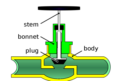
Packing in a sliding-stem valve fits in a section of the valve body called the bonnet, shown in this simplified diagram of a single-ported, stem-guided globe valve:

Here, the packing material takes the form of several concentric rings, stacked on the valve stem like washers on a bolt. These packing rings are forced down from above by the packing flange to apply a compressive force around the circumference of the valve stem.
This compressive force is necessary to generate mechanical stress in the packing material to make it seal tightly against the stem of the valve and the interior wall of the bonnet.
Two nuts threaded onto studs maintain proper force on the packing rings. Care must be taken not to over-tighten these nuts and over-compress the packing material, or else the packing will create excessive friction on the valve stem.
Not only will this friction impede precise valve stem motion, but it will also create undue wear on the stem and packing, increasing the likelihood of future packing leakage. Insufficient packing flange force will lead to poor sealing, with process fluid potentially leaking past the packing and out of the valve.
A closer look at the bonnet shows a multitude of components working together to form a low friction, pressure-tight seal for the moving valve stem:

In this diagram, we see two sets of packing rings separated by a metal piece called a lantern ring. The lantern ring acts as a spacer allowing lubricant introduced through the lubrication port to enter into both packing sets from the middle of the bonnet.
The packing shown here is “loaded” by the compressive force exerted by the packing follower. The only elasticity in this particular system resides in the packing material itself. This is called stationary loading, otherwise known as jam packing. Over time, as the packing material wears and fatigues, the packing follower must be re-compressed by carefully tightening the packing nuts.
One must be very careful when torquing the packing nuts on a stationary-loaded packing set. Insufficient torque (which translates into insufficient stress applied to the packing) will result in process fluid leakage. Excessive torque (causing excessive stress on the packing) will result in high valve stem friction and premature packing failure.
The latter scenario is what one usually finds in industrial settings, where well-intentioned but uninformed personnel over-tighten valve packing in an effort to prevent leaks. The proper remedy for a packing assembly that leaks despite having been properly torqued is replacement, not further tightening.
An alternative to “stationary” loading is to insert a metal spring into the packing assembly, so that the elasticity of the spring helps to maintain an appropriate amount of packing stress as the packing material wears and ages. This is called live loading, examples of which are shown here:

In one of these examples we see a coil spring inside the bonnet used to live-load the packing. In the other example we see a set of spring-steel washers known as a Belleville spring.
Belleville springs have a concave profile, giving them resistance to compression along the shaft axis. These spring washers are always stacked in opposed pairs (concave against concave, convex against convex) so the washers have room to compress.
Photographs taken of an actual valve packing assembly removed from the bonnet (left), and reassembled on the valve stem (right) reveal the structure of the packing and associated components.

There is no lantern ring in this packing assembly, but there is a coil spring. This makes it a live-loaded packing as opposed to a jam packing.
In packing applications requiring external lubrication, a stem packing lubricator may be connected to the lubrication port on the bonnet. This device uses a long, threaded bolt as a piston to push a quantity grease into the packing assembly:

To operate a lubricator, the hand valve on the lubricator is first secured in the closed (shut) position, then the bolt is fully unscrewed until it falls out of the lubricator body.
An appropriate lubricating grease is squeezed into the bolt hole in the lubricator body, and the bolt threaded back into place until hand-tight. Using a wrench or socket to tighten the bolt a bit more (generating pressure in the grease) and opening the hand valve allows grease to enter the packing chamber.
The bolt is then screwed in fully, pushing the entire quantity of grease into the packing. As a final step, the hand valve is fully shut so there is no way for process liquid to leak out past the bolt threads.
The two most common packing materials in use today are Teflon (PTFE) and graphite. Teflon is the better of the two with regard to fluid sealing, stem friction, and stem wear.
Teflon is also quite resistant to attack from a wide variety of chemical substances. Unfortunately, it has a limited temperature range and cannot withstand intense nuclear radiation (making it unsuitable for use near reactors in nuclear power plants).
Graphite is another self-lubricating packing material, and it has a far greater temperature range than Teflon as well as the ability to withstand harsh nuclear radiation, but creates much more stem friction than Teflon.
Graphite packing also has the unfortunate property of permitting galvanic corrosion between the stem and bonnet metals due to its electrical conductivity. Sacrificial zinc washers are sometimes added to graphic packing assemblies to help mitigate this corrosion, but this only postpones rather than prevents corrosive damage to the stem.
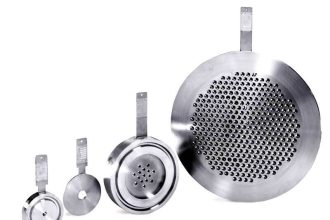
The following photographs show samples of woven graphite (left) and Teflon (right) “rope” packing, longer pieces of which would normally be found bent around valve stems to form seals.
The graphite packing has a shiny finish and flakes easily, while the Teflon packing is plain white in color and maintains its integrity. Both feel slippery to the touch:

Hybrid packing materials, such as carbon-reinforced Teflon, have been developed in an attempt to combine the best characteristics of both materials.
A legacy valve packing material is asbestos, woven into packing rings much the same way as graphite fibers are woven into modern packing rings.
Asbestos is a mineral, which made it suitable for high-temperature process applications. Its electrical non-conductivity eliminated the galvanic corrosion problem inherent to graphite.
Unfortunately, its classification as a hazardous substance precludes its use as a packing material for contemporary applications.
Also Read : Control Valve Installation, Maintenance, Disassembly & Reassembly


Excellent! Thank you for sharing.