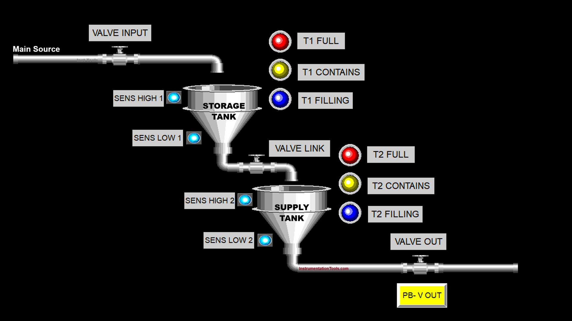
This article will discuss an automatic filling system for two tanks using the Omron PLC programming. The dual-tank system is designed to regulate the automatic flow of liquid between the storage tank and the supply tank, maintaining the liquid level in each tank within predetermined minimum and maximum limits. The storage tank receives liquid from the main source, while the supply tank delivers liquid to the next process. The system prioritizes filling to ensure the storage tank remains replenished. It also provides indicators regarding the tank conditions.
Program Objective
Step-by-step process :
1. System Initialization:
a. Check the liquid level in Tank 1 and Tank 2.
b. Determine the initial status of all valves:
- Input Valve (to Tank 1): Closed
- Inter-Tank Valve (Tank 1 to Tank 2): Closed
- Output Valve (from Tank 2): Closed
2. Filling Tank 1:
a. If Tank 1 level < minimum threshold:
- Open the input valve to fill Tank 1.
b. If Tank 1 level ≥ maximum threshold:
- Close the input valve.
3. Filling Tank 2 from Tank 1:
a. Check the two main conditions to open the inter-tank valve:
- Tank 2 is not full (level < maximum threshold)
- Tank 1 has sufficient liquid (level > minimum threshold)
b. If both conditions are met:
- Open the inter-tank valve.
c. If either condition is not met (Tank 2 is full or Tank 1 is being filled):
- Close the inter-tank valve.
4. Releasing Liquid from Tank 2:
a. If Tank 2 ≥ minimum operational level:
- Open the output valve to release the liquid.
b. If Tank 2 < minimum level:
- Close the output valve.
5. Automatic Looping Process:
This process runs in a continuous loop to maintain:
- Tank 1 within its minimum and maximum levels (storage function)
- Tank 2 filled as needed (feeder/output function
Storage and Supply Tank System
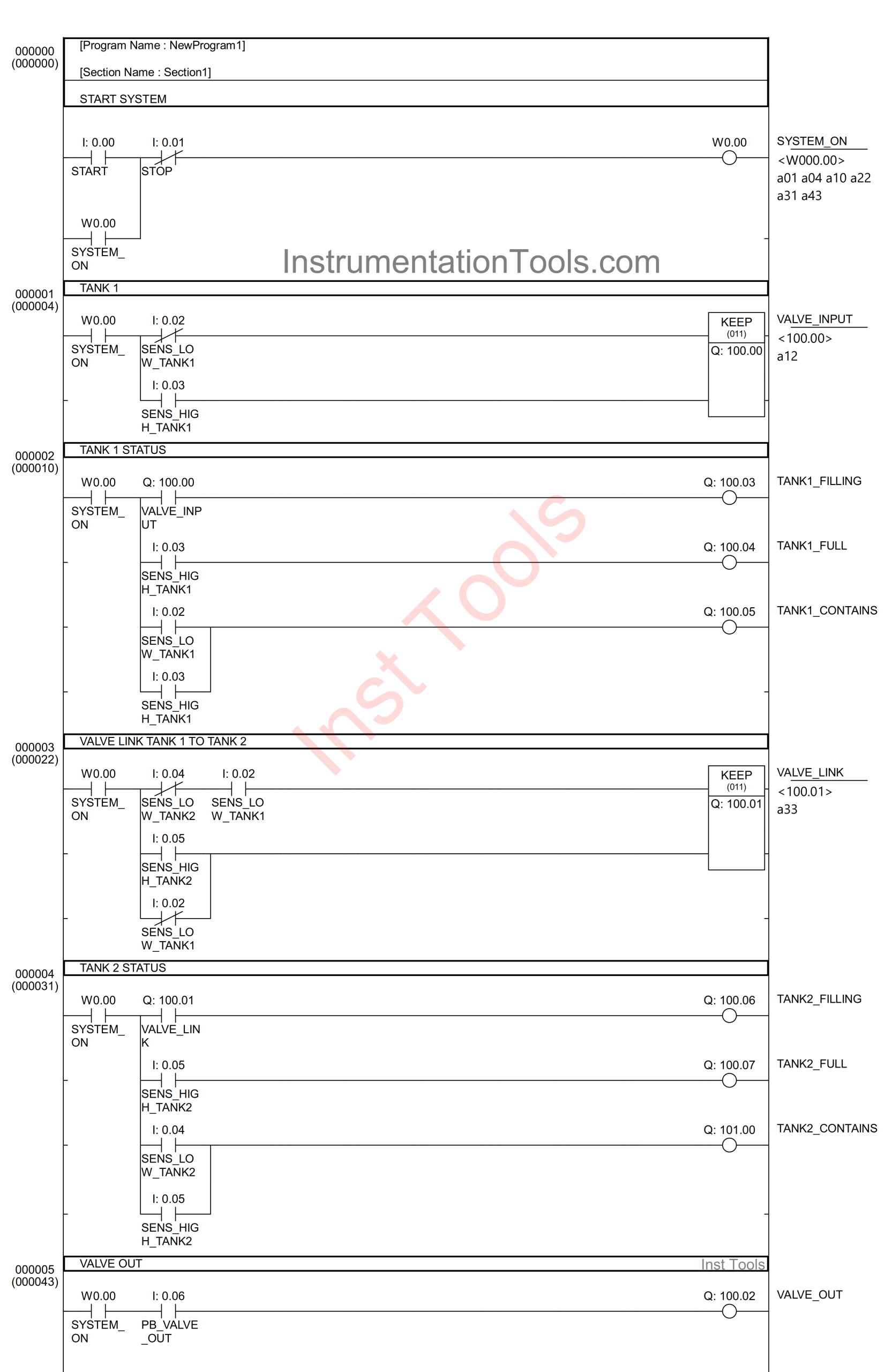
Here is the complete PLC program for the storage and supply tank system.
IO Mapping Details
| S.No. | Comment | Input (I) | Output (Q) | Memory Bit |
|---|---|---|---|---|
| 1 | START | 0.00 | ||
| 2 | STOP | 0.01 | ||
| 3 | SENS_LOW_TANK1 | 0.02 | ||
| 4 | SENS_HIGH_TANK1 | 0.03 | ||
| 5 | SENS_LOW_TANK2 | 0.04 | ||
| 6 | SENS_HIGH_TANK2 | 0.05 | ||
| 7 | PB_VALVE_OUT | 0.06 | ||
| 8 | VALVE_INPUT | 100.00 | ||
| 9 | VALVE_LINK | 100.01 | ||
| 10 | VALVE_OUT | 100.02 | ||
| 11 | TANK1_FILLING | 100.03 | ||
| 12 | TANK1_FULL | 100.04 | ||
| 13 | TANK1_CONTAINS | 100.05 | ||
| 14 | TANK2_FILLING | 100.06 | ||
| 15 | TANK2_FULL | 100.07 | ||
| 16 | TANK2_CONTAINS | 101.00 | ||
| 17 | SYSTEM_ON | W0.00 |
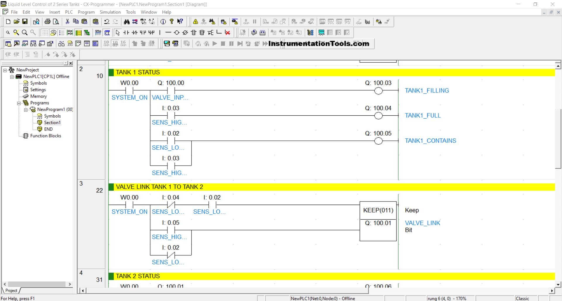
PLC Programming
RUNG 0 (START SYSTEM)
In this Rung, if the START (0.00) button is pressed, then the memory bit SYSTEM_ON(W0.00) will be in a HIGH state. Because it uses Latching, the memory bit SYSTEM_ON (W0.00) will remain in a HIGH state even though the START (0.00) button has been released.
The memory bit SYSTEM_ON(W0.00) will be in a LOW state if the STOP (0.01) button is pressed.
RUNG 1 (TANK 1)
In this Rung, if the NO contact of the memory bit SYSTEM_ON(W0.00) is in a HIGH state and the NC contact of the SENS_LOW_TANK1 (0.02) sensor is in a LOW state, then the VALVE_INPUT (100.00) output will be OPEN.
Because it uses the KEEP(001) instruction, the VALVE_INPUT (100.00) output will remain OPEN even though the NC contact of the SENS_LOW_TANK1 (0.02) sensor is in the HIGH state. The VALVE_INPUT (100.00) output will be CLOSED if the NO contact of the SENS_HIGH_TANK1 (0.03) sensor is in the HIGH state.
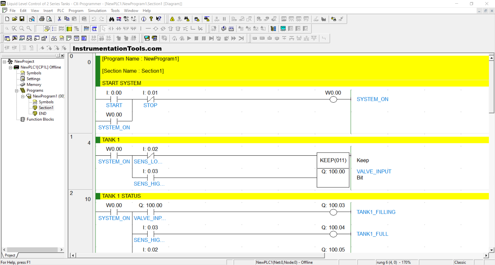
RUNG 2 (TANK 1 STATUS)
When the NO contact of the memory bit SYSTEM_ON(W0.00) and VALVE_INPUT (100.00) are in the HIGH state, then the TANK1_FILLING (100.03) output will be ON.
When the NO contact of the SENS_HIGH_TANK1 (0.03) sensor is in the HIGH state, then the TANK1_FULL (100.04) output will be ON.
And, if the NO contact of the SENS_LOW_TANK1 (0.02) or SENS_HIGH_TANK1 (0.03) sensors is in the HIGH state, then the TANK1_CONTAINS (100.05) output will be ON.
RUNG 3 (VALVE LINK TANK 1 TO TANK 2)
In this Rung, if the NO contact of the memory bit SYSTEM_ON (W0.00) and the SENS_LOW_TANK1 (0.02) sensor are in the HIGH state, then the VALVE_LINK (100.01) output will be OPEN.
Because it uses the KEEP(001) instruction, the VALVE_LINK (100.01) output will remain OPEN even though the NC contact of the SENS_LOW_TANK2 (0.04) sensor is in the HIGH state or the NO contact of the SENS_LOW_TANK1 (0.02) sensor is in the LOW state.
The VALVE_LINK (100.01) output will be CLOSED if the NO contact of the SENS_HIGH_TANK2 (0.05) sensor is in the HIGH state or the NC contact of the SENS_LOW_TANK1 (0.02) sensor is in the LOW state.
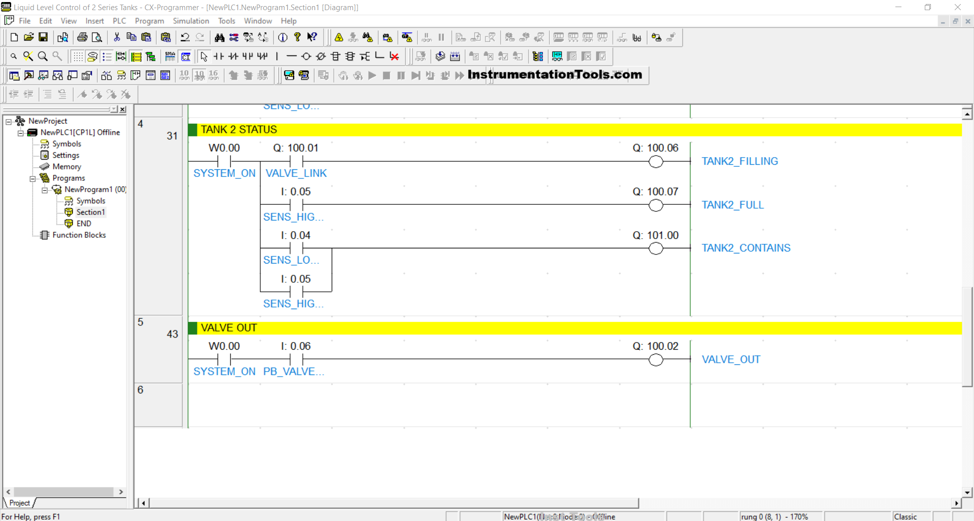
RUNG 4 (TANK 2 STATUS)
When the NO contact of the memory bit SYSTEM_ON (W0.00) and VALVE_LINK (100.01) are in the HIGH state, the TANK2_FILLING (100.06) output will be ON.
When the NO contact of the SENS_HIGH_TANK2 (0.05) sensor is in the HIGH state, the TANK2_FULL (100.07) output will be ON.
And, if the NO contact of the SENS_LOW_TANK2 (0.04) or SENS_HIGH_TANK2 (0.05) sensors is in the HIGH state, the TANK2_CONTAINS (101.01) output will be ON.
RUNG 5 (VALVE OUT)
In this Rung, when the NO contact of the memory bit SYSTEM_ON (W0.00) is in HIGH state and the PB_VALVE_OUT (0.06) button is pressed, the VALVE_OUT (100.02) output will be OPEN.
Read Next:
- Shift Register in Omron PLC Program with Example
- PLC Programming for Door Lock with Delay Problem
- PLC Exercise and Solution for Water Fountain Control
- How to Blink Lights in Ladder Logic with Programming
- Ladder Logic PLC Examples: Automatic Sanitizer