PLC Programming Example on multi-motor control for beginners using Schneider Electric EcoStruxure Machine Expert Basic PLC software.
Please note, that this PLC example is for engineering students who are interested in learning and practicing the PLC exercises. The real-time industrial PLC programs will be designed with more safety and protection features.
PLC Programming Example on Multi-Motor
Design a PLC ladder logic for the following application.
We are using three toggle switches to control three motors.
- If Switch 1 is ON, then Motor I, Motor II, and Motor III will be ON.
- If Switch 2 is ON, then Motor I and Motor II will be ON.
- If Switch 3 is ON, then Motor I, Motor II, and Motor III will be Off.
Digital Inputs
The following digital inputs (DI) are required in this example program. The assigned PLC DI addresses are also mentioned.
Switch 1: I0.0
Switch 2: I0.1
Switch 3: I0.2
Digital Outputs
The following digital outputs (DO) are required in this example program. The assigned PLC DO addresses are also mentioned.
Motor 1: Q0.0
Motor 2: Q0.1
Motor 3: Q0.2
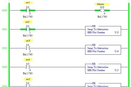
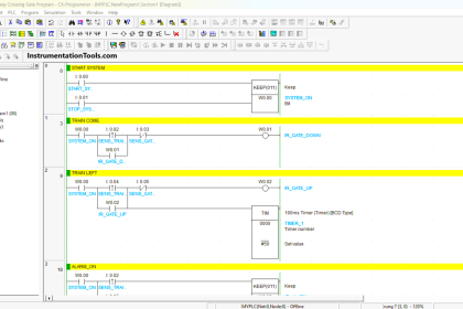
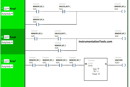
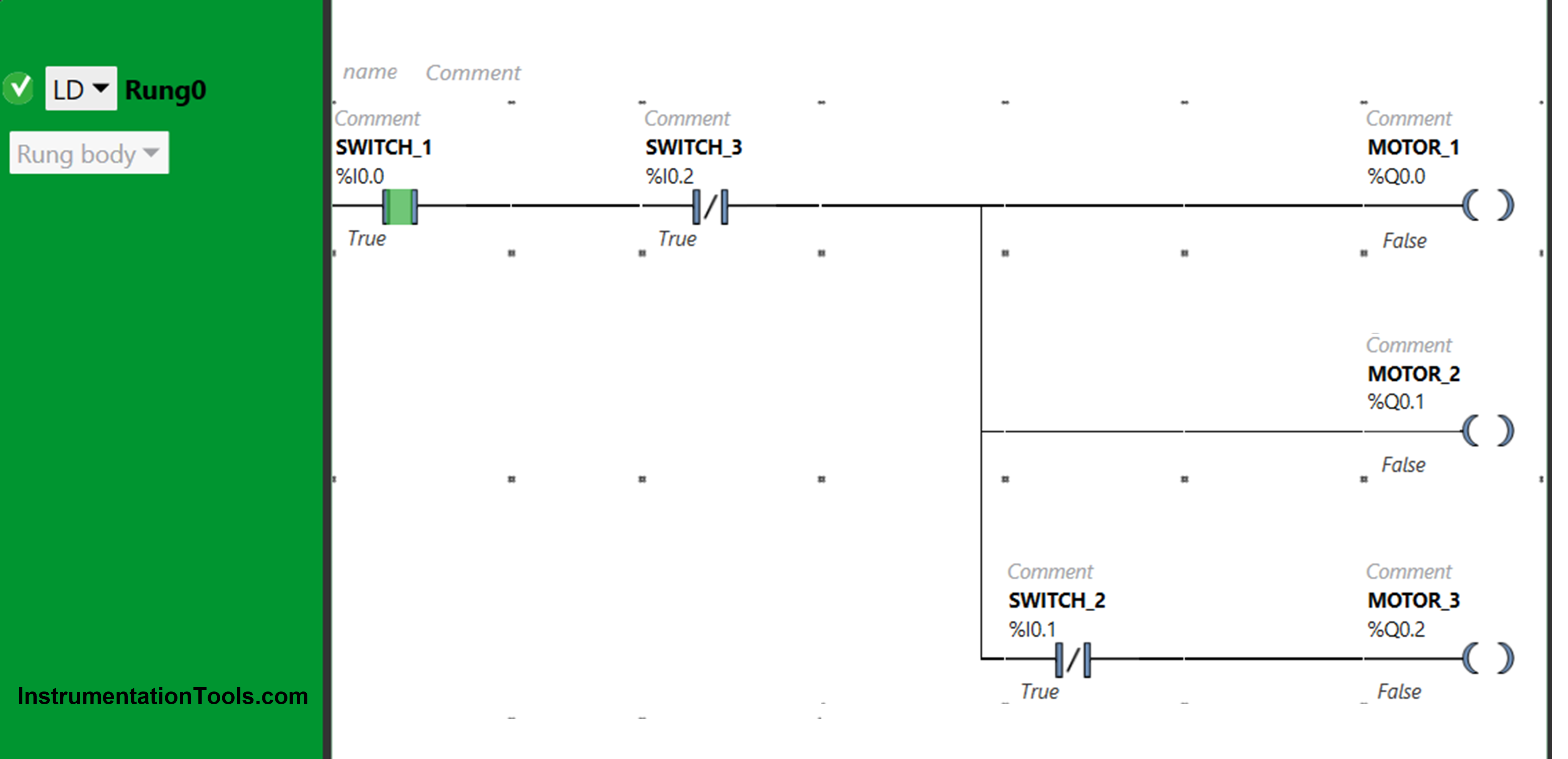
Ladder Diagram for Multi-Motor Control
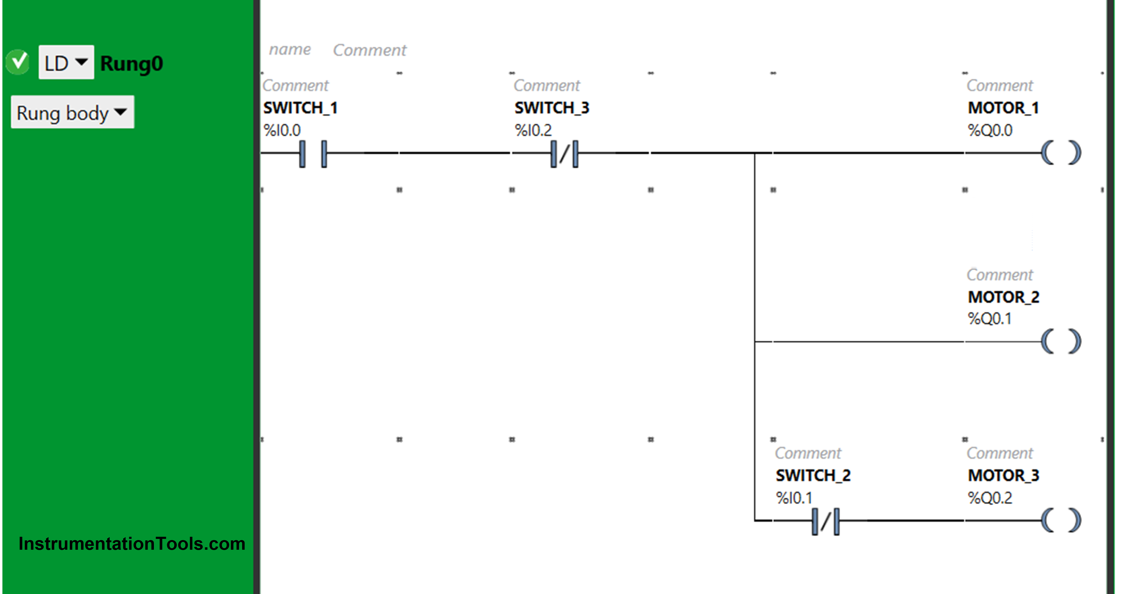
Program Description
- For this application, we used Ecostruxure Machine Expert Basic v1.2 software for programming.
- In the above program, we have used Normally Open Contact for Switch 1 (I0.0), Normally Closed Contacts for Switch 2 (I0.1) and Switch 3 (I0.2)
- Switch 1 and switch 3 are connected in series for Motor 1 and Motor 2, thus implementing AND logic gate.
- For Motor 3, switch 1, switch 2 and switch 3 are connected in series, thus implementing AND logic gate.
- For Motor 1 and Motor 2 to be ON, switch 1 should be ON and switch 3 should be OFF.
- When switch 1 is ON, switch 2 and switch 3 are OFF, Motor 3 will be ON.
- Turning ON Switch 3 will turn OFF all the Motors i.e., Motor 1, Motor 2 and Motor 3 will be OFF.
- Motor 3 will turn OFF, when Switch 2 is turned ON.
- When switch 1 is turned ON, all the motors will turn ON because the current will also pass through switch 2 and switch 3 as these are Normally Closed Contacts.
- Without turning OFF switch 1, motor 1 and motor 2 will still remain ON but motor 3 will turn OFF, when switch 2 is turned ON. On turning Switch 2 ON, it will not pass current to motor 3.
- All the motors will turn OFF when switch 3 is turned ON, even if other switches are ON.
When Switch 1 is ON
The current flows through switch 1 as it is in true state. In false state, switch 3 and switch 4 also pass current to the outputs.
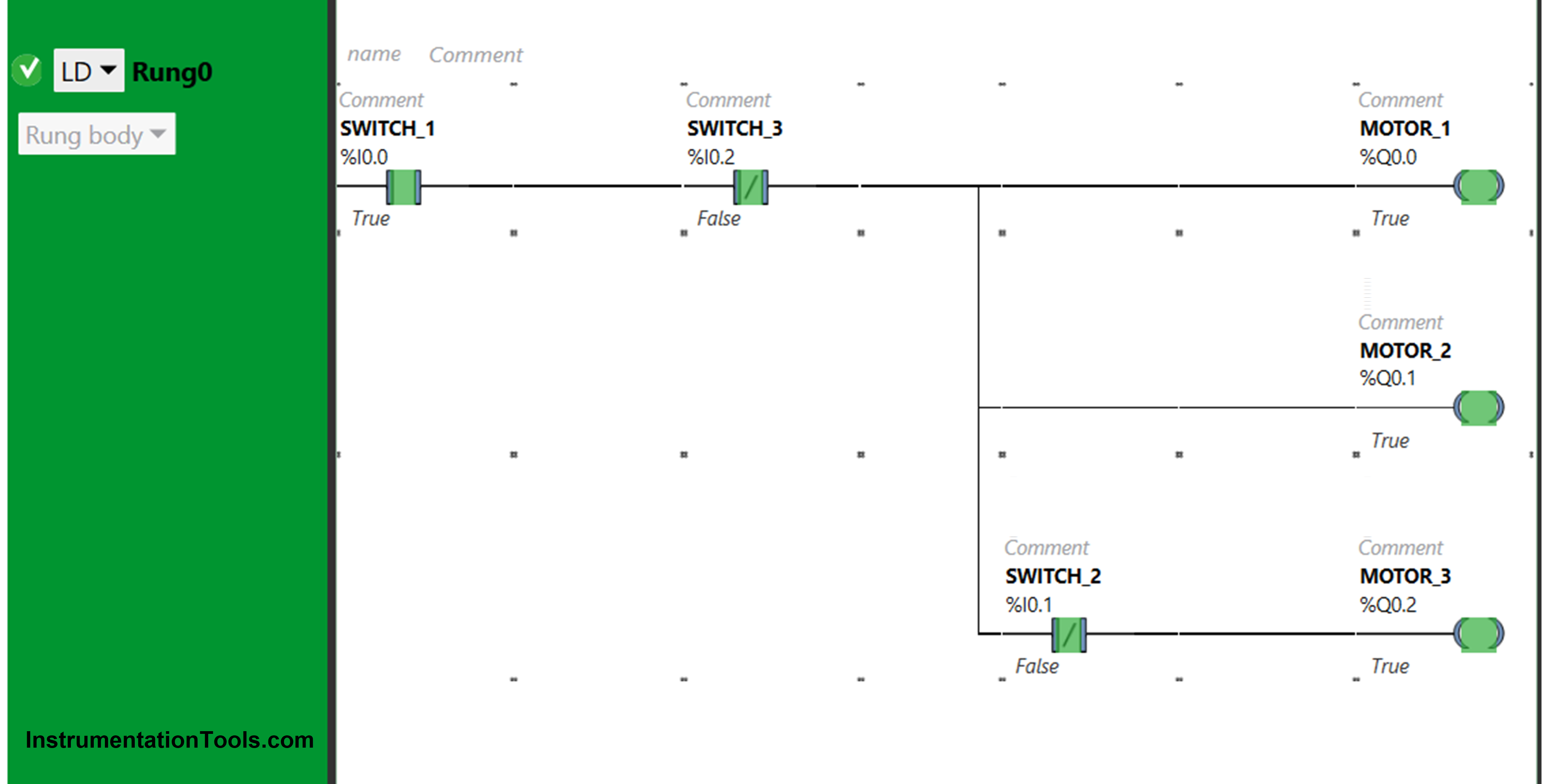
When Switch 2 is ON
The current does not flow through switch 2 when it is turned ON. In true state Normally Closed contact breaks the circuit.
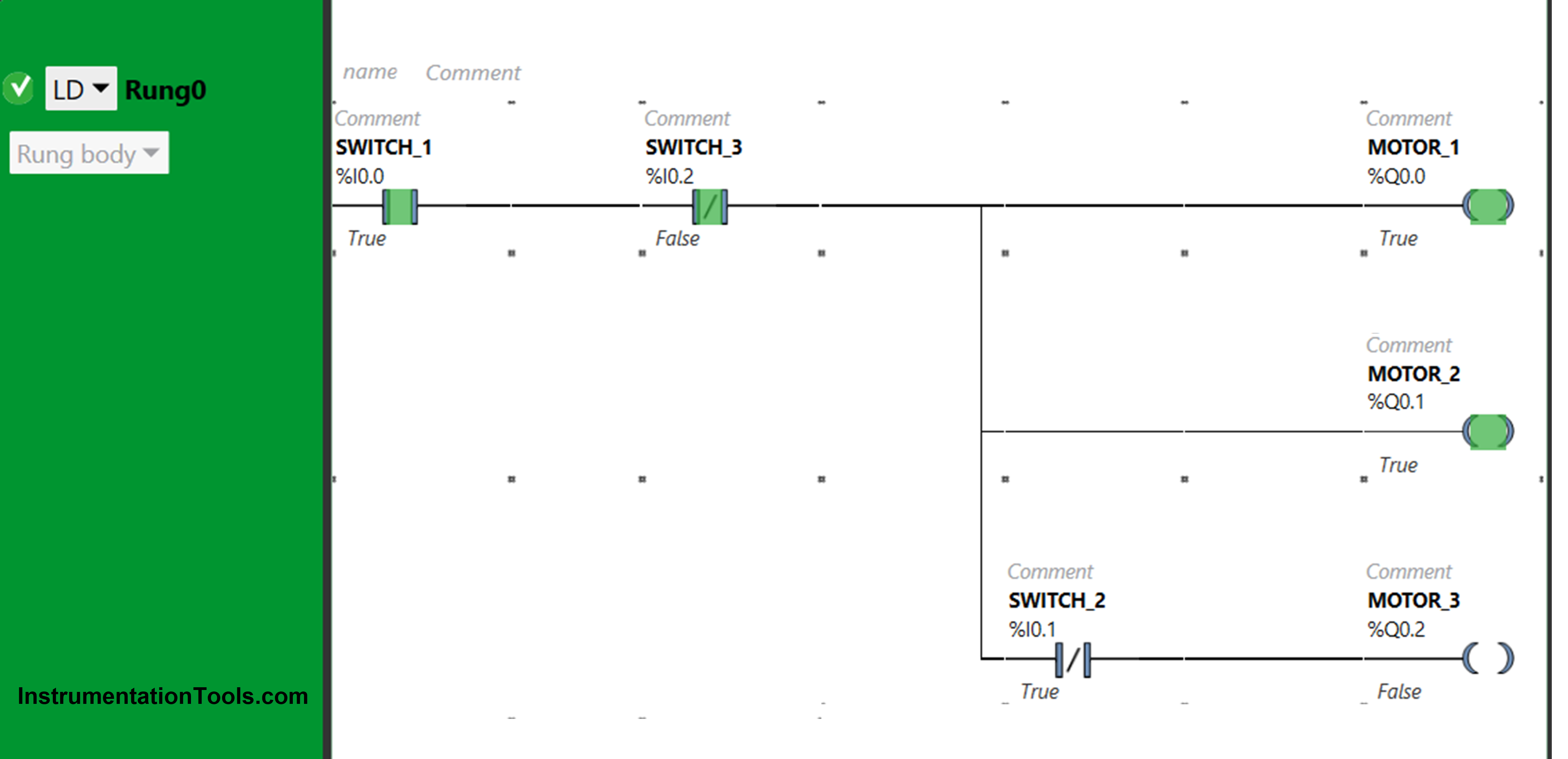
When Switch 3 is ON
Switch 3 is a Normally closed contact. When turned On, it will not allow current to pass through it. As a result, none of the output will be ON.
PLC Programming Video
You can watch the below PLC programming video to understand this example program. You can follow the steps from scratch and learn the program.
If you liked this article, then please subscribe to our YouTube Channel for Electrical, Electronics, Instrumentation, PLC, and SCADA video tutorials.
You can also follow us on Facebook and Twitter to receive daily updates.
Read Next:
- Most Asked Questions on SCADA
- Instruction List in PLC Programming
- Top Best Practices of PLC Wiring
- Site Commissioning Steps for PLC
- Top 100 PLC Projects for Students