This is a PLC Program for heating and bending glass tubes.
Heat and Bend Glass Tubes
Problem Description
- In glass industry heated glass tubes are passing in a process line having a particular length which are to be bent.
- We need to bend glass tube in U-shape. These bended glass tube is used for fluorescent bulbs.
- Implement this process in PLC using ladder diagram programming language.
Problem Diagram

Problem Solution
For this process, we will consider two pneumatic rods that force the glass tube through metal support for the bending process.
During this process metal support is continuously heated so that glass does not break while bending.
When the bending process is completed, two cutters are used to cut the bent glass.
Proximity switch detects the length to be cut by the cutter in the cutting process.
Metal supports are mounted close to each other so the bending rod and glass tube can pass through it.
List of Inputs and Outputs
Inputs List
- START PB :- I0.0
- STOP PB :- I0.2
- Glass detector :- I0.3
- Glass length detector (proximity) :- I0.6
Outputs List
- Bend valve :- Q0.0
- Cutter :- Q0.2
- Return valve :- Q0.3
M memory
- Master coil :- M0.0
- Relay coil 1:- M0.1
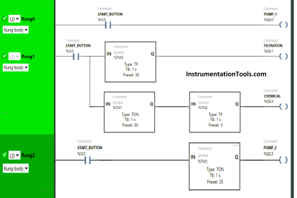
PLC Ladder Logic to heat and bend glass tubes
Logic Description
For this application we used S7-300 PLC and TIA portal software for programming.
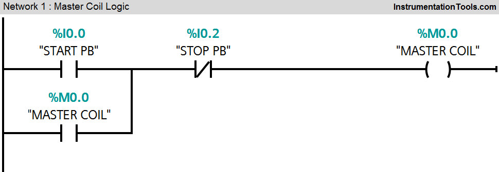
Network 1:
Master coil will be ON (M0.0) when START PB (I0.0) will be pressed and master coil can be stopped by pressing STOP PB (I0.2).
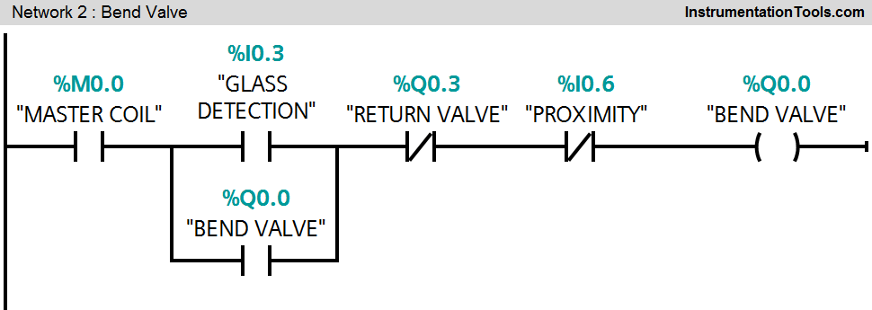
Network 2:
When glass detector sensor (I0.3) detects the glass, bending process will be ON or bend vale (Q0.0) will be ON.
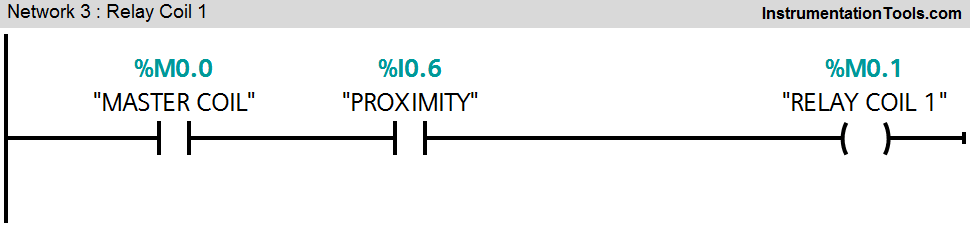
Network 3:
When glass length sensor is detected (I0.6), relay coil 1(M0.1) will be ON for next command.
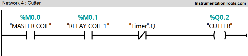
Network 4:
If relay coil 1(M0.1) is ON, cutter (Q0.2) will be ON
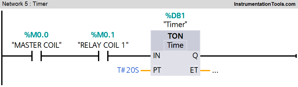
Network 5:
Timer will start to count time when relay coil 1 (M0.1) is ON after 20sec delay (here we assumed time for cutting) cutter (Q0.2) will turn OFF.
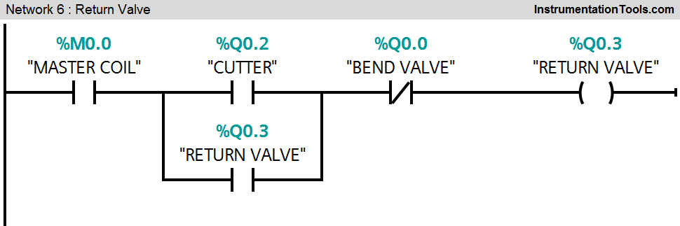
Network 6:
When cutter output is ON (Q0.2) and bend valve (Q0.0) is OFF, return valve (Q0.3) will be ON.
Note :- Above application may be different from actual application. This example is only for explanation purpose only. We can implement this logic in other PLC also. This is the simple concept of heating and bending of glass tube in industry, we can use this concept in other examples also.
All parameters considered in example are for explanation purpose only, parameters may be different in actual applications. Also all interlocks are not considered in the application.
If you liked this article, then please subscribe to our YouTube Channel for PLC and SCADA video tutorials.
You can also follow us on Facebook and Twitter to receive daily updates.
Read Next:
- Latching & unlatching Circuit
- PLC Tank Heating Control using Heater
- Controlling Sequence of Conveyors
- PLC Automatic Heating and Mixing of Products
- Food Processing Industry PLC Example


I/O addressing mismatching as per you description and ladder diagram . Please correct it.