This PLC example on manufacturing line assembly is an intermediate-level PLC program prepared for the students to learn the programming.
Note: The PLC programming example is specifically prepared for the students to learn the PLC programs.
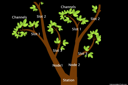
Manufacturing Line Assembly
Problem Statement
Design a PLC ladder logic for the following application.
We are using one toggle switch and three sensors to control 3 stations.
The product should move through 3 assembly stations, with each station operating for 15 seconds.
PLC Programming Training
Watch the video below to understand the PLC program objective in detail and its solution.
PLC Program Inputs
The PLC program inputs are shown below.
Start Button: I0.0
Sensor 1: I0.1
Sensor 2: I0.2
Sensor 3: I0.3
PLC Program Outputs
The PLC program outputs are shown below.
Station 1: Q0.0
Station 2: Q0.1
Station 3: Q0.2
Ladder Logic
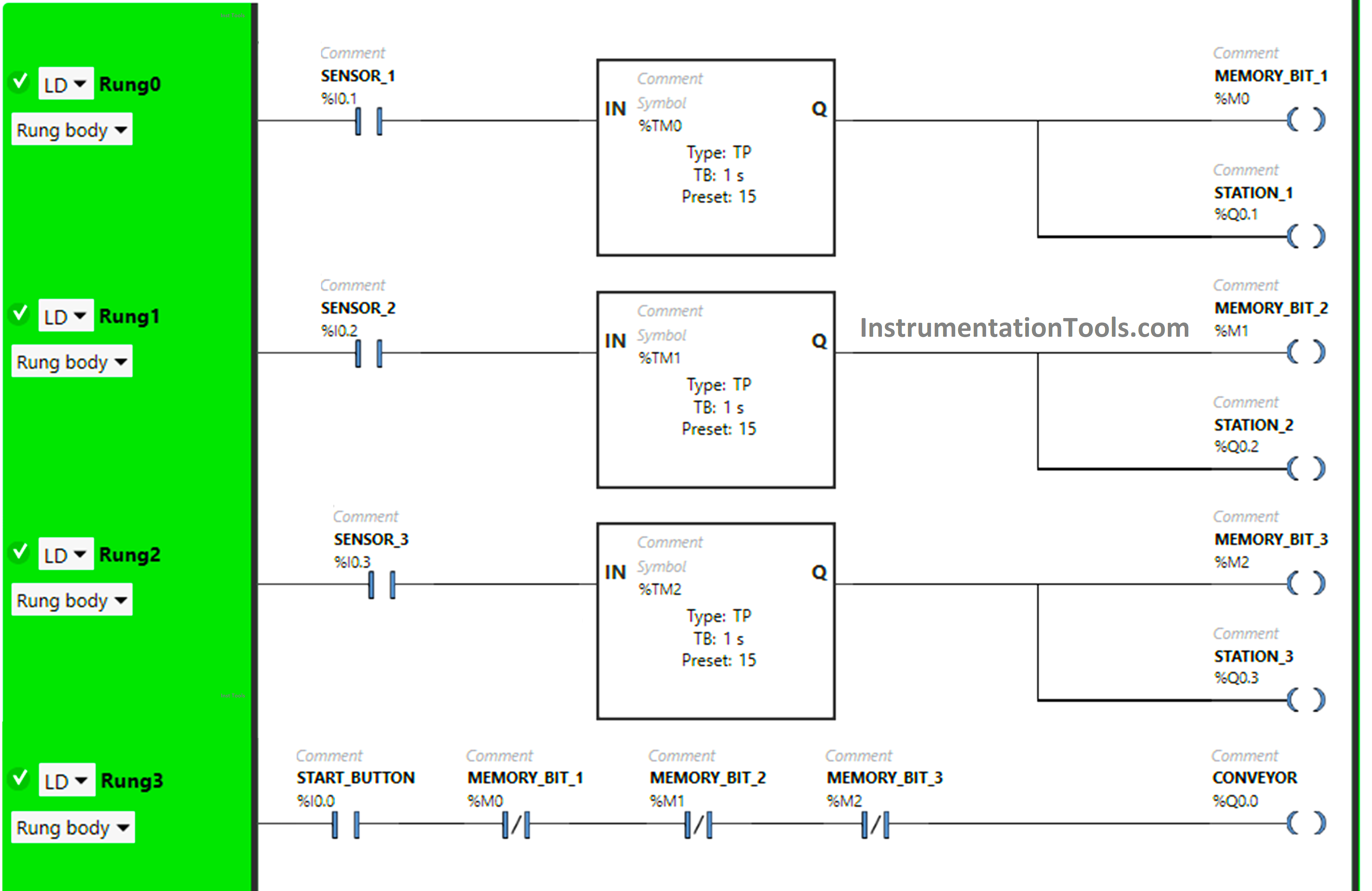
Logic Explanation
We have used Normally Open Contacts for Start Button(I0.0), Sensor 1 (I0.1), Sensor 2 (I0.2), and Sensor 3 (Q0.3).
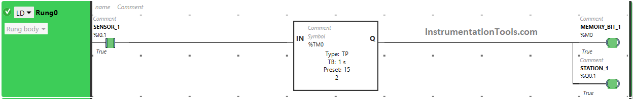
In Rung0:
1) Normally Open Contact is used for Sensor 1 (I0.1) to Turn ON Memory Bit 1 (M0) and the output station 1 (Q0.1).
2) Timer Function Block type TP is used to Turn ON Memory Bit 1 (M0) and the output station 1 (Q0.1) for a limited time.
In Rung1:
1) Normally Open Contact is used for Sensor 2 (I0.2) to Turn ON Memory Bit 2 (M1) and the output station 2 (Q0.2).
2) Timer Function Block type TP is used to Turn ON Memory Bit 2 (M1) and the output station 2 (Q0.2) for a limited time.
In Rung2:
1) Normally Open Contact is used for Sensor 3 (I0.3) to Turn ON Memory Bit 3 (M2) and the output station 3 (Q0.3).
2) Timer Function Block type TP is used to Turn ON Memory Bit 3 (M2) and the output station 3 (Q0.3) for a limited time.
In Rung3:
1) Normally Open Contact is used for the Start Button (I0.0) to Turn ON the output Conveyor (Q0.0).
2) Normally Closed Contacts are used for Memory Bit 1 (M0), Memory Bit 2 (M1), and Memory Bit 3 (M2) to Turn ON the output Conveyor (Q0.0).
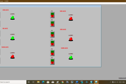
Test Results
Let’s simulate our PLC logic and show the results below. Note: we showed the part of the simulation logic instead of the complete program.
When the Product reaches station 1


When the Start Button (I0.0) is turned ON in Rung3, the output Conveyor (Q0.0) turns ON ( Conveyor starts moving) as Normally Open Contact used for start Button (I0.0) will be in True state and passes the signal to turn ON the output Conveyor (Q0.0).
In the False state, Normally Closed Contacts used Memory Bit 1 (M0), Memory Bit 2 (M1), and Memory Bit 3 (M2) in Rung3 will also pass the signal to turn ON the output Conveyor (Q0.0) and the output Conveyor (Q0.0) turns ON (Conveyor starts moving).
When Sensor 1 (I0.1) gets activated in Rung0 ( Product reaches Station 1), Memory Bit 1 (M0) turns ON, and also, the output Station 1 (Q0.1) turns ON (Machines at Station 1 starts working).
When Memory Bit 1 (M0) turns ON in Rung0, Normally Closed Contact used for Memory Bit 1 (M0) in Rung3 will be in a True state and does not allow the signal to pass through it and the Conveyor (Q0.0) turns OFF ( Conveyor stops at Station 1 ).
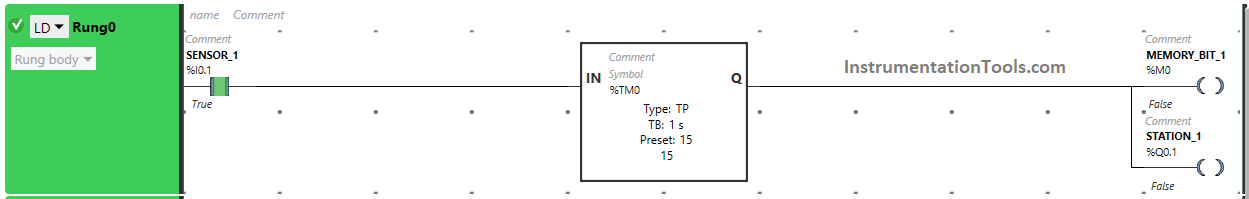
In Rung0, Memory Bit 1 (M0) and the output Station 1 (Q0.1) turn off after some time as Timer Function Block type TP is used to Turn ON the output Station 1 (Q0.1) and Memory Bit 1 (M0) for a limited time. The time is set to 15 seconds.
After 15 s, the output Station 1 (Q0.1) and Memory Bit 1 (M0) will turn OFF (Machines at Station 1 finished their work).
When Memory Bit 1 (M0) turns OFF in Rung0, Normally Closed Contact used for Memory Bit 1 (M0) will be in a False state and allow the signal to pass through it and the output Conveyor (Q0.0) turns ON (Conveyor starts moving).
When the Product reaches station 2
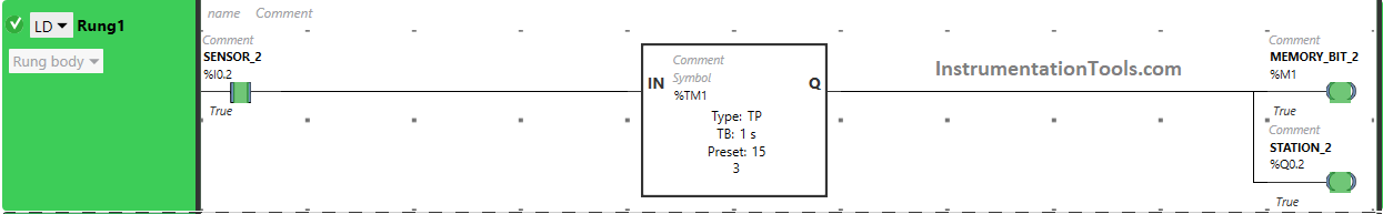


After leaving Station 1, When Sensor 2 (I0.2) gets activated in Rung1 ( Product reaches Station 2), Memory Bit 2 (M1) turns ON, and also, the output Station 2 (Q0.2) turns ON (Machines at Station 2 starts working).
When Memory Bit 2 (M1) turns ON in Rung1, Normally Closed Contact used for Memory Bit 2 (M1) in Rung3 will be in a True state and does not allow the signal to pass through it and the Conveyor (Q0.0) turns OFF ( Conveyor stops at Station 2 ).
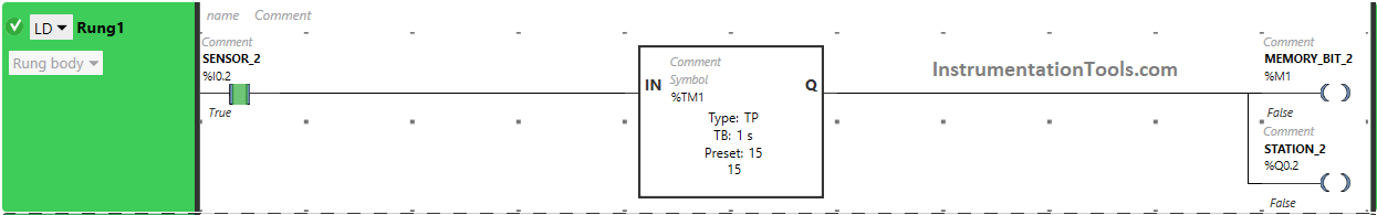
In Rung1, Memory Bit 2 (M1) and the output Station 2 (Q0.2) turn off after some time as Timer Function Block type TP is used to Turn ON the output Station 2 (Q0.2) and Memory Bit 2 (M1) for a limited time.
The time is set to 15 seconds. After 15 s, the output Station 2 (Q0.2) and Memory Bit 2 (M1) will turn OFF (Machines at Station 2 finished their work).
When Memory Bit 2 (M1) turns OFF in Rung1, Normally Closed Contact used for Memory Bit 2 (M1) will be in a False state and allow the signal to pass through it and the output Conveyor (Q0.0) turns ON (Conveyor starts moving).
When the Product reaches station 3
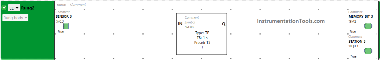


After leaving Station 2, When Sensor 3 (I0.3) gets activated in Rung2 (Product reaches Station 3), Memory Bit 3 (M2) turns ON, and also, the output Station 3 (Q0.3) turns ON (Machines at Station 3 starts working).
When Memory Bit 3 (M2) turns ON in Rung2, Normally Closed Contact used for Memory Bit 3 (M2) in Rung3 will be in a True state and does not allow the signal to pass through it and the Conveyor (Q0.0) turns OFF ( Conveyor stops at Station 3 ).
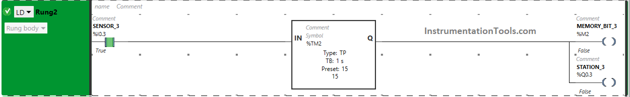
In Rung2, Memory Bit 3 (M2) and the output Station 3 (Q0.3) turn OFF after some time as Timer Function Block type TP is used to Turn ON the output Station 3 (Q0.3) and Memory Bit 3 (M2) for a limited time. The time is set to 15 seconds. After 15 s, the output Station 3 (Q0.3) and Memory Bit 3 (M2) will turn OFF (Machines at Station 3 finished their work).
When Memory Bit 3 (M2) turns OFF in Rung2, Normally Closed Contact used for Memory Bit 3 (M2) will be in a False state and allow the signal to pass through it and the output Conveyor (Q0.0) turns ON (Conveyor starts moving).
If you liked this article, please subscribe to our YouTube Channel for PLC and SCADA video tutorials.
You can also follow us on Facebook and Twitter to receive daily updates.
Read Next:
- Timers in PLC Programming Tutorials
- Latching and Unlatching in PLC Programming
- Electrical Cabinet Air Conditioner Maintenance
- Motor control using PLC Ladder Programming
- User-Defined Data Types and Function Blocks