Objective : To understand the basic concept of PLC Valve Control Ladder Logic.
Target Users : Students, Technicians, Freshers, Trainee engineers.

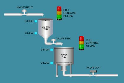
Note : Barrier or Relay not shown in above figure.
Lets list out the required PLC digital inputs and digital output signals :
PLC Digital Inputs :
- Valve Open Feedback
- Valve Close Feedback
PLC Digital output :
- Valve Energize command
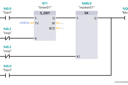
PLC Valve Control Ladder Logic Programming
Any pneumatic valve requires instrument air supply for its operation. A air filter regulator is used to remove any liquid or particulate matter present in the instrument air supply and to set the required air supply to the valve.
The output of air filter regulator is connected to valve actuator via a Solenoid valve. This solenoid valve is used to control i.e. ON/OFF the instrument air supply to the valve actuator.

Consider solenoid valve (SOV) is Normally Close (NC) type. In normal position, the SOV is in off position or de-energized state, so the instrument air supply will be blocked as SOV is Normally closed. if SOV is energized i.e. PLC sends the signal then SOV energizes and becomes normally open (NO), so allows instrument air supply through its.
Some people often confuses about Solenoid valve and Valve actuator. These both are different, SOV controls (ON/OFF) the instrument air supply and Valve actuator controls the position of the valve either fully open or fully close.
ON/OFF valve are equipped with either proximity switches or limit switches to sense the valve position either fully open or fully close. so these are connected to the PLC digital inputs. So PLC can know the valve status in the field either fully open or fully close and displays to the operator via graphics.
Consider our ON/OFF valve is Normally Open type i.e. valve is in Open position. so by default Open Feedback will be sent to the PLC or we can say Open feedback limit switch or proximity switch will be energized and close feedback switch is in de-energize state.
Lets say PLC sends an Digital output command to the ON/OFF valve (via a barrier or a relay). Say we have 24V DC powered solenoid valve mounted on the ON/OFF valve.
Also Read : How PLC controls a Motor ?
Generally either a barrier or a relay is placed after the PLC digital output module. consider we have a barrier, first barrier receives the PLC digital output module command (PLC command is Barrier input) then the barrier energizes its output (Barrier output) and barrier sends the 24V DC power to the respective ON/OFF valve.
The purpose of barrier or relay is used to isolate the PLC & Field signals or for safety purpose or to amplify the power/voltage signals.
Now ON/OFF valve receives the PLC command i.e. it received the 24V DC power to the solenoid valve from the barrier. so now solenoid valve will be energized and changes to Normally Open (NC) state. Now solenoid valve passes the instrument air supply to the valve actuator as it becomes Normally open.
The valve actuator receives the instrument air supply and moves the valve stem accordingly and the valve position will change from fully open state to full close state. When the ON/OFF valve starts the stem movement then immediately Open Feedback will be gone (proximity switch will not detect any object mounted on the stem).
After starts valve stem movement and before reaching close position, both open & close feedbacks will not be available to the PLC and we call this as transition state. After the ON/OFF valve fully closed then close feedback switch (proximity or limit) will be energized and close feedback signal will be sent to the PLC and displayed to the operator.
Note : Sometimes ON/OFF valve may stuck in between, so operator will not receive any feedback on the graphics, as both open & close feedback switches will only detect either fully open or fully close states of the valve. Its not possible to detect any Intermediate state of the valve.
Say now PLC withdraws the Output command to the ON/OFF valve i.e. barrier input will be turned off, so barrier will de-energized or barrier output will be OFF, 24V DC power will be disconnected/removed to the Solenoid valve.
As solenoid valve power removed, SOV changes its state from NO to NC. Solenoid valve becomes Normally Closed i.e. Instrument air supply to the valve actuator will be stopped or disconnected. So ON/OFF valve also comes into its original state i.e. Open state.
PLC can send output command signal based on some logics or real time input signals. for example : if level of a drum reaches high alarm then drum feed ON/OFF valve has to be closed.
Details of ON/OFF Valve :
In our example we considered a pneumatic on/off valve. First we see the list of components in the valve & its purpose.
a. Air Filter Regulator :
Air Filters are used to remove liquid water and particulate matter from compressed air sources. These are ‘mechanical filters’ and do not remove oil vapors or chemical contaminants in vapor form. Click here for Principle & Animation.
b. Solenoid Valve :
A solenoid valve is an electro-mechanical controlled valve. The valve features a solenoid, which is an electric coil with a movable ferromagnetic core in its center. This core is called the plunger.
In rest position, the plunger closes off a small orifice. An electric current through the coil creates a magnetic field. The magnetic field exerts a force on the plunger. As a result, the plunger is pulled toward the center of the coil so that the orifice opens. This is the basic principle that is used to open and close solenoid valves.
Also Read :
c. Open Feedback & Close Feedback :
A proximity switch is one detecting the proximity (closeness) of some object.
By definition, these switches are non-contact sensors, using capacitive, inductive, magnetic, electric, or optical means to sense the proximity of the valve position either open or close.
Also Read :
d. Valve Actuator :
A valve actuator is a device that produces force to open or close the valve utilizing a power source. This source of power can be manual (hand, gear, chain-wheel, lever, etc.) or can be electric, hydraulic or pneumatic.
Also Read :
e. Instrument Air Supply :
Compressed & Dried air supply for the valve.
PLC Tutorials :
What is Programmable Logic Controller ?
What is Ladder Diagram Programming ?
History of Programmable Logic Controllers
Mis-conceptions of PLC Ladder Logic
Contacts and coils in PLC
Digital Input and Output Modules
Analog I/O and Network I/O
PLC Input/Output Modules
Memory Mapping in PLC
Analog Input Scaling
PLC Example with Switches
Counter Instructions
Timer Instructions
Math instructions
Data Instructions
Ladder Logic Questions
If you liked this article, then please subscribe to our YouTube Channel for PLC and SCADA video tutorials.
You can also follow us on Facebook and Twitter to receive daily updates.


Thank You so much sir. Wonderful article as usual. I am your fan from very long time. Your my true guide & friend.
Good job, Thank you.
Hi,
all articles are very interesting and usable I have learnt a lot from this.
All articles are explained well and too helpful
Thank you for all info.
I’m I&C engineer from Libya. I’v been working for power plant…
Thanks a lot .