Inst ToolsInst ToolsInst Tools
  • Courses
  • Automation
    • PLC
    • Control System
    • Safety System
    • Communication
    • Fire & Gas System
  • Instrumentation
    • Design
    • Pressure
    • Temperature
    • Flow
    • Level
    • Vibration
    • Analyzer
    • Control Valve
    • Switch
    • Calibration
    • Erection & Commissioning
  • Interview
    • Instrumentation
    • Electrical
    • Electronics
    • Practical
  • Q&A
    • Instrumentation
    • Control System
    • Electrical
    • Electronics
    • Analog Electronics
    • Digital Electronics
    • Power Electronics
    • Microprocessor
  • Request
Search
  • Books
  • Software
  • Projects
  • Process
  • Tools
  • Basics
  • Formula
  • Power Plant
  • Root Cause Analysis
  • Electrical Basics
  • Animation
  • Standards
  • 4-20 mA Course
  • Siemens PLC Course
Reading: Solenoid Valve Working Animation
Share
Notification Show More
Font ResizerAa
Inst ToolsInst Tools
Font ResizerAa
  • Courses
  • Design
  • PLC
  • Interview
  • Control System
Search
  • Courses
  • Automation
    • PLC
    • Control System
    • Safety System
    • Communication
    • Fire & Gas System
  • Instrumentation
    • Design
    • Pressure
    • Temperature
    • Flow
    • Level
    • Vibration
    • Analyzer
    • Control Valve
    • Switch
    • Calibration
    • Erection & Commissioning
  • Interview
    • Instrumentation
    • Electrical
    • Electronics
    • Practical
  • Q&A
    • Instrumentation
    • Control System
    • Electrical
    • Electronics
    • Analog Electronics
    • Digital Electronics
    • Power Electronics
    • Microprocessor
  • Request
Follow US
All rights reserved. Reproduction in whole or in part without written permission is prohibited.
Inst Tools > Blog > Animation > Solenoid Valve Working Animation

Solenoid Valve Working Animation

Last updated: April 13, 2019 12:20 pm
Editorial Staff
Animation Control Valves How It Works Solenoid Valve
2 Comments
Share
1 Min Read
SHARE

Solenoid Valve Animation

Solenoid Valve Animation

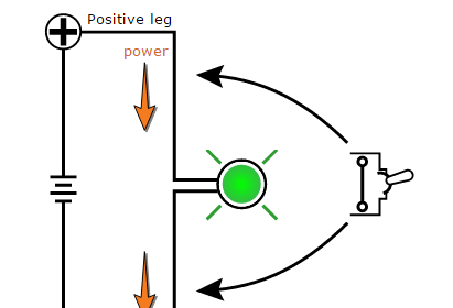
1. The above shown animation is an example of normally closed solenoid operated valve.

2. When there is no supply voltage to SOV then it will be in Normally Closed condition (default).

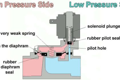
3. When the Switch was closed then power will be passed through the Solenoid coil, then energizes the coil. The energized solenoid coil acts as magnet and lifts the core or plunger ( Center Part of Solenoid) of the solenoid.

4. As the core or plunger of solenoid moves towards upsides, this movement creates a open flow.

5. When the Switch was opened .i.e. power supply is disconnected, then solenoid coil de-energizes and magnetic field also stopped. Then the plunger will be pushed back to its original position with the help of a spring, this movement stops the flow.

6. Thus the solenoid valve will open/close as per the solenoid valve coil magnetization.

Articles You May Like :

Relay Loop Back Circuit

PLC Latching Function

Solenoid Problems

4-20mA Loop Power

Energize to Safe Loop

Don't Miss Our Updates
Be the first to get exclusive content straight to your email.
We promise not to spam you. You can unsubscribe at any time.
Invalid email address
You've successfully subscribed !

Continue Reading

What is Ball Valve ?
Valve Actuator Bench Set
Argonite Fire Suppression System Working Principle
Open Tank Level Measurement using DP Transmitters Animation
What is a Pneumatic Actuator ?
How is Pressure Drop Calculated through a Valve ?
Share This Article
Facebook Whatsapp Whatsapp LinkedIn Copy Link
Share
2 Comments
  • AAditya says:
    October 8, 2015 at 6:10 pm

    Very very useful..Thanku!!

    Reply
  • Sagar nakar says:
    September 19, 2016 at 5:57 am

    ???good articles

    Reply

Leave a Reply Cancel reply

Your email address will not be published. Required fields are marked *

Stay Connected

128.3kFollowersLike
69.1kFollowersFollow
210kSubscribersSubscribe
38kFollowersFollow

Categories

Explore More

Interview Questions on Control Valves
What is Split Range Control Loop ?
Instrumentation Inspection Report
Rotameter Working Principle and Animation
Electrical Actuators
NDIR Gas Analyser Working Principle
DIN Valve Connectors – Definition, Types
Safety Relief Valve Questions & Answers

Keep Learning

ball Valve Animation

Basics of Ball Valves

Functional Testing of Control Valve Positioners

Functional Testing of Control Valve Positioners

Flapper nozzle system

What is Flapper Nozzle System ?

Erratic Stroking Control Valves

Erratic Stroking Control Valves Delaying the Shutdown Plant Restart

Understanding the Scan Cycle of SIEMENS PLC

Understanding the Scan Cycle of SIEMENS PLC

LVDT-Operation-Principle-Animation

LVDT Working Principle Animation

What is Cavitation

What is Cavitation? What are the Causes?

Densitometers Principle

Vibrating Tube Densitometers Working Principle

Learn More

McLeod Gauge Working Principle

McLeod Gauge Working Principle

Tilt Level Switch Theory

Tilt Level Switch Working Principle

Count the Number of Cartons in a Storage Area PLC Logic

Count the Number of Cartons in a Storage Area PLC Logic

Block Diagram

Block Diagram

Digital Electronics Multiple Choice Questions

Ripple Counter Objective Questions

Types of Switches

Electrical Switches Principle & Types

What is ELCB

What is ELCB? Principle, Advantages, Disadvantages, Applications

Current Limiting Resistor

Resistors Principle & Applications

Menu

  • About
  • Privacy Policy
  • Copyright

Quick Links

  • Learn PLC
  • Helping Hand
  • Part Time Job

YouTube Subscribe

Follow US
All rights reserved. Reproduction in whole or in part without written permission is prohibited.
Welcome Back!

Sign in to your account

Username or Email Address
Password

Lost your password?