We most often come across four way traffic jam in our city. This PLC ladder logic gives the solution to control city traffic using programmable logic control.
4 Way Traffic Light Control
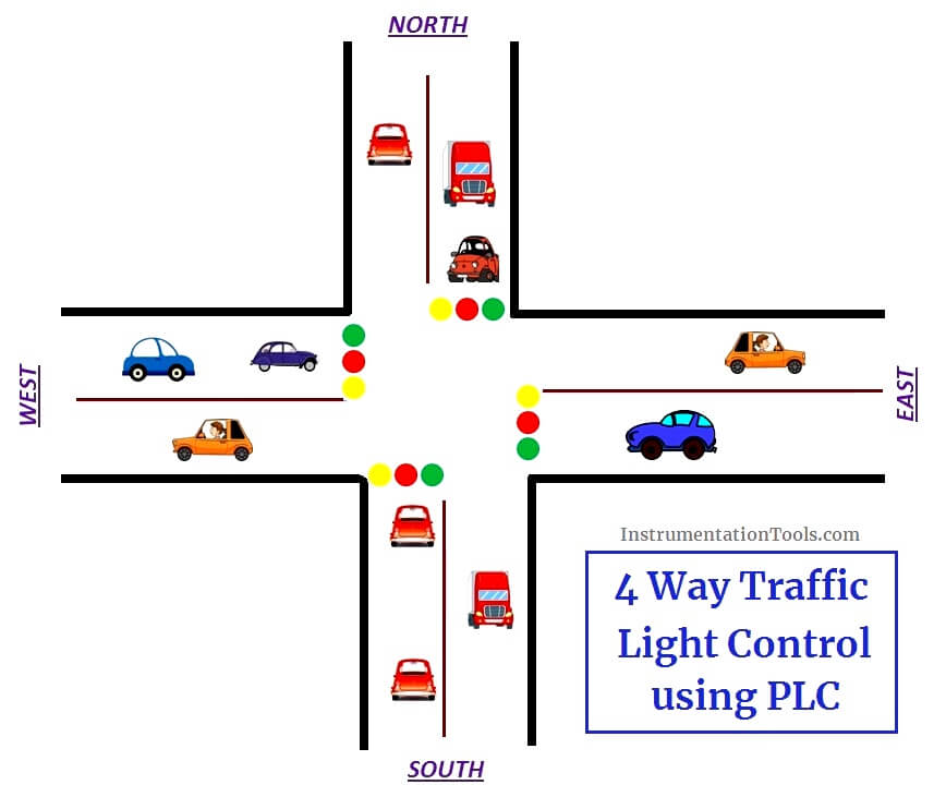
Problem Solution
- They are so many ways to write a program for traffic light control ex: sequencer output method but in this normal input, outputs and timers are used.
- Timers are used to give time delay for output to turn on and off.
- Reset using timer done bit at the end to run the program continuously.
- Program done in AB RSLogix 500 Software.
List of Inputs and Outputs
| S.no | Address | Name | Input/Output |
| 1 | I:0/0 | Start | Input |
| 2 | I:0/1 | Stop | Input |
| 3 | B3.0 | Memory | Memory |
| 4 | O:0/0 | East Green | Output |
| 5 | O:0/1 | North Red | Output |
| 6 | O:0/2 | West Red | Output |
| 7 | O:0/3 | South Yellow | Output |
| 8 | O:0/4 | East Yellow | Output |
| 9 | O:0/5 | North Yellow | Output |
| 10 | O:0/6 | North Green | Output |
| 11 | O:0/7 | East Red | Output |
| 12 | O:0/8 | West Yellow | Output |
| 13 | O:0/9 | West Green | Output |
| 14 | O:0/10 | South Yellow | Output |
| 15 | O:0/11 | South Green | Output |
Sequence of Operation
Below tabular column gives the Steps or sequence of outputs to turn ON the traffic system lamps (RED, GREEN, YELLOW)
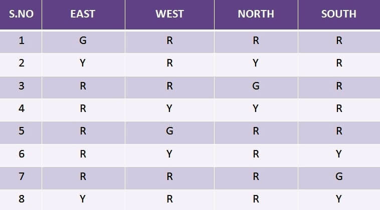
PLC Ladder Logic
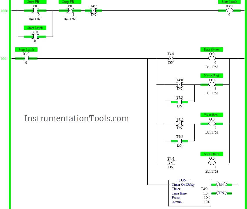
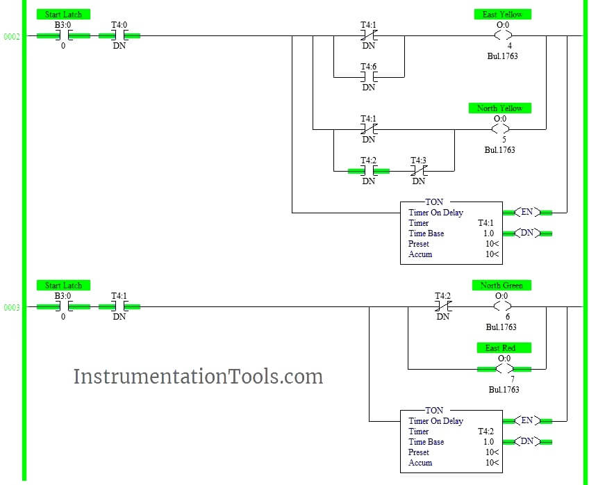

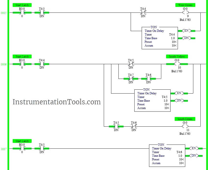

Logic Description
RUNG000
Latching rung to operate the system through Master Start and Stop PB.
RUNG001
Starting the timer to turn on output East Green ,North-South-West are in red. Parallel circuits are added to turn ON/OFF the output in up next sequence.
RUNG 0002
Turning on North Yellow and East Yellow. Parallel circuits are added to turn ON/OFF the output in up next sequence.
Rung 0003
Turn on East Red and North Green.
Rung 0004-0005-0006-0007
Same procedures followed to turn on further outputs.( Refer Above Tabular column for sequence of operation)
RUNG 0008
Timer (T4:7) done bit is used to restart the cycle from beginning
Program runs continuously until STOP PB is pressed
Time delay of 10s has given using timers.
Note: We can reduce the number of timers using comparator block
Conclusion:
The above explained 4 ways traffic light control using PLC is for example only. It may vary from real time. We can use this example program to understand the working of timers and Interlocking function in AB PLC.
If you liked this article, then please subscribe to our YouTube Channel for PLC and SCADA video tutorials.
You can also follow us on Facebook and Twitter to receive daily updates.
Read Next:






IS IT POSSIBLE TO DO THIS WITH JUST ONE TIMER
Can you combine North/South, East/West instructions for neatness and simplicity?