Resistance Temperature Detectors (RTDs) rely on the predictable and repeatable phenomena of the electrical resistance of metals changing with temperature.
The temperature coefficient for all pure metals is of the same order – 0.003 to 0.007 ohms/ohm/°C. The most common metals used for temperature sensing are platinum, nickel, copper and molybdenum. While the resistance – temperature characteristics of certain semiconductor and ceramic materials are used for temperature sensing, such sensors are generally not classified as RTDs.
How are RTDs constructed?
RTDs are manufactured in two ways: using wire or film. Wire RTDs are a stretched coil of fine wire placed in a ceramic tube that supports and protects the wire. The wire may be bonded to the ceramic using a glaze. The wire types are generally the more accurate, due to the tighter control over metal purity and less strain related errors. They are also more expensive.
Film RTDs consist of a thin metal film that is silk-screened or vacuum spluttered onto a ceramic or glassy substrate. A laser trimmer then trims the RTD to its correct resistance value.
Film sensors are less accurate than wire types, but they are relatively inexpensive, they are available in small sizes and they are more robust. Film RTDs can also function as a strain gauge – so don’t strain them! The alumina element should be supported by grease or a light elastomer, but never embedded in epoxy or mechanically clamped between hard surfaces.
RTDs cannot generally be used in their basic sensing element form, as they are too delicate. They are usually built into some type of assembly, which will enable them to withstand the various environmental conditions to which they will be exposed when used. Most commonly this is a stainless steel tube with a heat conducting grease (that also dampens vibration). Standard tube diameters include 3, 4.5, 6, 8, 10, 12 and 15 mm and standard tube lengths include 250, 300, 500, 750 and 1000 mm.
Characteristics of RTDs
Metal RTDs have a response defined by a polynomial:
Where R0 is the resistance at 0°C, “t” in the temperature in Celsius, and “a”, “b” and “c” are constants dependent on the characteristics of the metal. In practice this equation is a close but not perfect fit for most RTDs, so slight modifications are often be made.
Commonly, the temperature characteristics of an RTD are specified as a single number (the “alpha”), representing the average temperature coefficient over the 0 to 100°C temperature range as calculated by:
Note: RTDs cover a sufficient temperature range that their response needs to be calibrated in terms of the latest temperature scale ITS90. For assistance with such calculations, see the RTD temperature calculator.
It is also of interest to note that the temperature coefficient of an alloy is frequently very different from that of the constituent metals. Small traces of impurities can greatly change the temperature coefficients. Sometimes trace “impurities” are deliberately added so as to swamp the effects of undesired impurities which are uneconomic to remove. Other alloys can be tailored for particular temperature characteristics. For example, an alloy of 84% copper, 12% Manganese and 4% Nickel has the property of having an almost zero response to temperature. The alloy is used for the manufacture of precision resistors.
Types of RTDs
While almost any metal may be used for RTD manufacture, in practice the number used is limited.
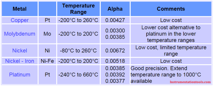
Platinum RTDs
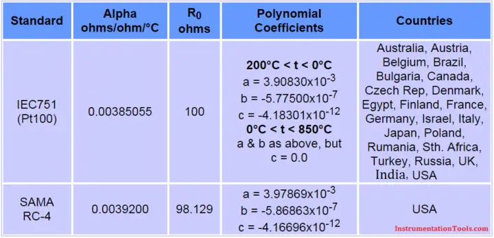
Platinum is by far the most common RTD material, primarily because of its long-term stability in air. There are two standard Platinum sensor types, each with a different doping level of ‘impurities’. To a large extent there has been a convergence in platinum RTD standards, with most national standards bodies adopting the international IEC751-1983, with amendment 1 in 1986 and amendment 2 in 1995. The USA continues to maintain its own standard.
All the platinum standards use a modified polynomial known as the Callendar – Van Dusen equation:
Platinum RTDs are available with two temperature coefficients or alphas – the choice is largely based on the national preference in you country, as indicated in the following table:
RTD Tolerance
The international IEC 751 standard specifies tolerance classes as indicated in the following table. While only Classes A and B are defined in IEC 751, it has become common practice to extended the Classes to C and D, which roughly double the previous error tolerance. The tolerance classes are often applied to other RTD types.
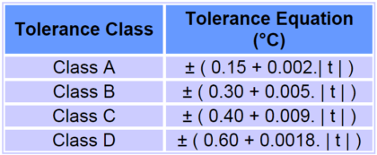
Where | t | indicated the magnitude of the temperature in Celsius (that is sign is dropped). Some manufacturers further subdivide their RTD Tolerance Classes into Tolerance Bands for greater choice in price performance ratios.
Characteristics of Platinum RTDs
The IEC751 specifies a number of other characteristics – insulation resistance, environmental protection, maximum thermoelectric effect, vibration tolerance, lead marking and sensor marking. Some of these are discussed below:
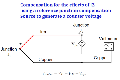
Thermoelectric Effect: A platinum RTD generally employs two metals – the platinum sensing element and copper lead wires, making it a good candidate for a thermocouple. If a temperature gradient is allows to develop along the sensing element, a thermoelectric voltage with a magnitude of about 7 µV /°C will be generated. This is only likely to be a problem with very high-precision measurements operating at low excitation currents.
Wiring Configurations and Lead Marking:
There are three wiring configurations that can be used for measuring resistance – 2, 3 and 4 wire connections.
IEC751 requires that wires connected to the same end of the resistor be the same colour – either red or white, and that the wires at each end be different.
Also Read: Difference between 2, 3 and 4 Wire RTD’s
Sensor Marking: IEC 751 stipulates that a sensor should be marked with its nominal R0 value, tolerance class, the wiring configuration and the allowable temperature range. An example marking is:
corresponding to 100 Ohm platinum, class A, 3 wire configuration and with a temperature range from -100°C to +200°C.
Measurement Current: Preferred measurement currents are specified as 1, 2 and 5 mA, although 5 mA is not allowed with class A sensors due to potential self-heating errors.
Nickel RTDs
Nickel sensors are preferred in cost sensitive applications such as air conditioning and consumer goods. Because cost is an issue, they are generally manufactured in higher resistance values of 1k or 2k ohms so that a simple two-wire connection can be used (rather than the 3 or 4 wire connections common with platinum types).
There appears to be no international standard covering the nickel RTD, although most manufacturers appear to follow IEC751 (which only deals with platinum devices) where appropriate. A resulting problem is that there appears to be no widely-accepted calibration for the nickel RTD.
One manufacturer of nickel RTDs recommends the following polynomial:
where a = 5.485×10⁻³ b = 6.650×10⁻⁶ d = 2.805×10⁻¹¹ and f = -2.000×10⁻¹⁷. The alpha for this part is 0.00672 ohms / ohm / °C
More common for low to medium precision measurement the simplification of the equation is used with a = alpha:
which is easily inverted for temperature:
where “a” is substituted for the alpha value.
Nickel is less chemically-inert that platinum and so is less stable at higher temperatures. Glass passivation can extend the useful temperature range to 200°C, but the nickel RTD is normally used for sensing in the environmental temperature range and in clear air.
Nickel – Iron RTDs
Lower in cost than the pure Nickel RTD, the Nickel-Iron RTD finds application in HVAC and other cost-sensitive applications. The alpha = 0.00518
Copper RTDs
Copper is rarely used specifically as a sensing element, but is often employed when a copper coil exists for other purposes. For example in a vibrating wire stain gauge a coil is required to “pluck” the wire and sense its vibration frequency. The same coil can be used to sense the temperature of the sensor so that its readings may be compensated for temperature induced drifts. Another application is in measuring the temperature of electric motor and transformer windings.
In these types of applications, where temperature sensing is a secondary function, care should be taken in winding the coil so that thermal expansion of the system does not induce significant strain gauge effects in the copper wire which may add to the uncertainty of the measurement.
There appears to be no international standard for copper RTDs, however an alpha = 0.00427 ohms / ohm / °C is commonly used. When the temperature range is small (say 0°C to 180°C) and the accuracy needs are not great, a simple linear function can be used:
Molybdenum has a temperature coefficient of expansion which almost perfectly matches that of alumina, making it an ideal material for film type of construction. The useful temperature range is typically -200°C to +200°C and the material’s alpha = 0.00300 ohms / ohm / °C.
Molybdenum RTDs are also available with an alpha = 0.00385 ohms / ohm / °C (achieved by doping with other metals) which makes it compatible with the standard Pt100 devices over a reduced temperature range and at a reduced cost.
Also Read: Calculate RTD Temperature Coefficient


Kindly give information about Pi Proprortional integral derivative
Kindly update one word questions for Instrument Technician . It’s very useful for all .