Inst ToolsInst ToolsInst Tools
  • Ask
  • Courses
  • Videos
  • Q & A
    • Interview
      • Instrumentation
      • Electronics
      • Electrical
      • Practical Questions
    • MCQ
      • Instrumentation MCQ
      • Electrical MCQ
      • Electronics MCQ
      • Control Systems MCQ
      • Analog Electronics MCQ
      • Digital Electronics MCQ
      • Power Electronics MCQ
      • Microprocessor MCQ
      • Multiple Choice Questions
  • EE
    • Electronics
      • Electronics Q & A
      • Electronic Basics
      • Electronic Devices & Circuits
      • Electronics Animation
      • Digital Electronics
    • Electrical
      • Electrical Basics
      • Electrical Q & A
      • Power Electronics
      • Electrical Machines
      • Electrical Animation
      • Power Systems
      • Switchgear & Protection
      • Transmission & Distribution
  • Measure
    • Control Valves
    • Calibration
    • Temperature
    • Pressure
    • Flow
    • Level
    • Analyzers
    • Switches
    • Vibration
    • Solenoid Valve
  • Control
    • PLC Tutorials
    • Control Systems
    • Safety Instrumented System (SIS)
    • Communication
    • Fire & Gas System
  • More
    • Design
    • Tools
    • Animation
    • Basics
    • Formulas
    • Standards
    • TextBooks
    • Common
    • Software
    • Excel Tools
    • Erection & Commissioning
    • Process Fundamentals
    • Videos
    • Books
Search
All rights reserved. Reproduction in whole or in part without written permission is prohibited.
Reading: PID with Practical Example
Share
Notification Show More
Font ResizerAa
Inst ToolsInst Tools
Font ResizerAa
  • Courses
  • PLC Tutorials
  • Control Systems
Search
  • Ask
  • Courses
  • Videos
  • Q & A
    • Interview
    • MCQ
  • EE
    • Electronics
    • Electrical
  • Measure
    • Control Valves
    • Calibration
    • Temperature
    • Pressure
    • Flow
    • Level
    • Analyzers
    • Switches
    • Vibration
    • Solenoid Valve
  • Control
    • PLC Tutorials
    • Control Systems
    • Safety Instrumented System (SIS)
    • Communication
    • Fire & Gas System
  • More
    • Design
    • Tools
    • Animation
    • Basics
    • Formulas
    • Standards
    • TextBooks
    • Common
    • Software
    • Excel Tools
    • Erection & Commissioning
    • Process Fundamentals
    • Videos
    • Books
Follow US
All rights reserved. Reproduction in whole or in part without written permission is prohibited.
Inst Tools > Blog > PLC Tutorials > PID with Practical Example

PID with Practical Example

PID means proportional, integral and the derivative is a controller used to control the processes. Learn with practical PLC example.

Last updated: March 4, 2021 11:13 am
Editorial Staff
PLC Tutorials
No Comments
Share
5 Min Read
SHARE

In this article, you will learn about PID instruction with the help of a practical example.

Here, I will consider a practical application to control a manipulate variable to maintain a set point of the process.

PID means proportional, integral and the derivative is a controller used to control the processes by adjusting the manipulated variable to keep process variable at a set-point.

Nowadays it is easier to work with PID as it comes inbuilt in PLC programming software with a lot of features.

Here, I will consider an example of one process. To maintain the process variable at a set-point I will write a PLC program.

PID with Practical Example

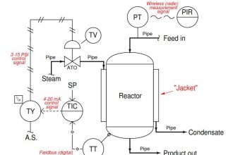
Let’s consider a temperature control loop in which I have to control the temperature.

Here, consider a range of the transmitter from 0 to 300 °C. I have one control valve in line to control the temperature.

So at 0% opening of the valve, the temperature will remain the same process temperature as it is. Now let’s say the temperature is 100 °C and at 100% control valve opening, the temperature of the process will rise to 300 °C.

Here, the temperature will rise to 2 degrees per percentage (%) of valve opening (assumption).

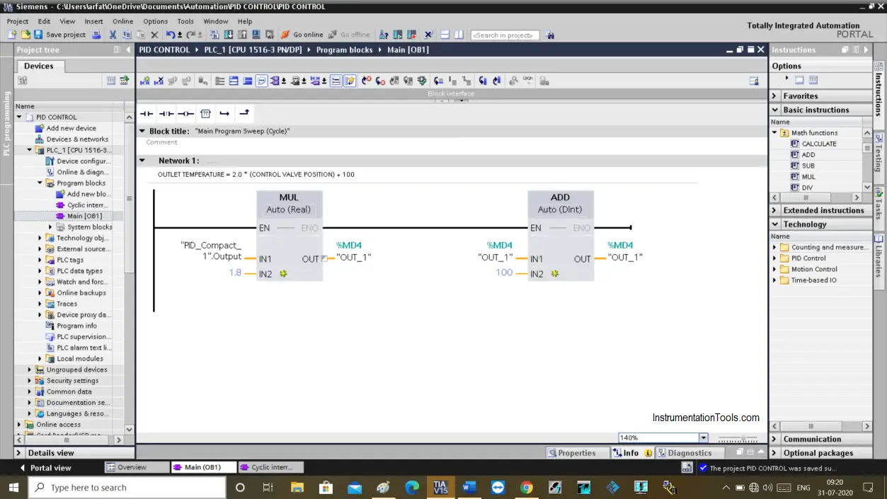
Outlet temperature will be given by the following equation,

Outlet temperature = 2 * (Control Valve Position) + 100

Here “2” is a temperature increment per percentage (%) of valve opening.

“100” is a starting range of temperature. As you know the minimum temperature a transmitter can measure for a given process is 100 °C. (assumed)

As per our calculation, we have to put the same equation in the PLC programming.

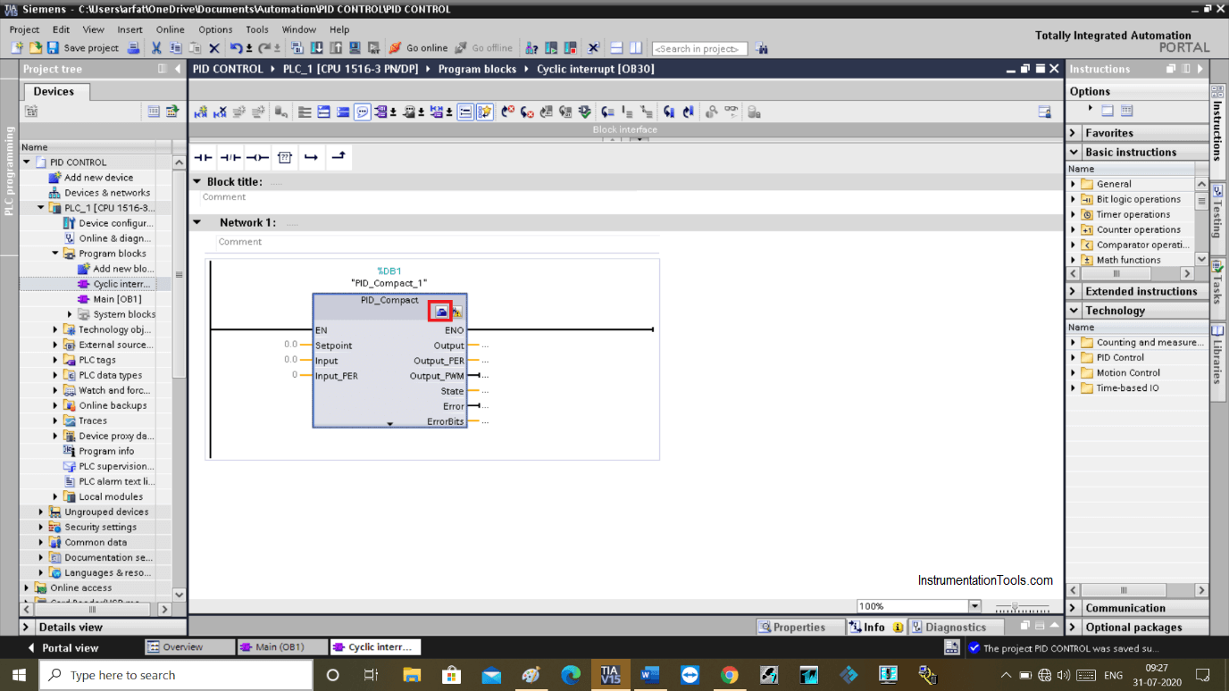
I already have covered the PID instruction introduction in my previous article, to program a PID block you have to create a cyclic OB.

Because you want your process to update at a specified time interval. For cyclic OB it usually stays at 1 second.

As you can see in the below window that I added the same equation in the main OB.

In the Multiplication instruction in “IN1”, I have used the output of the PID block which is a control valve position.

PID with Practical Example

Now, let’s add a parameter in the PID block which I have added to cyclic OB for continuous update of process data.

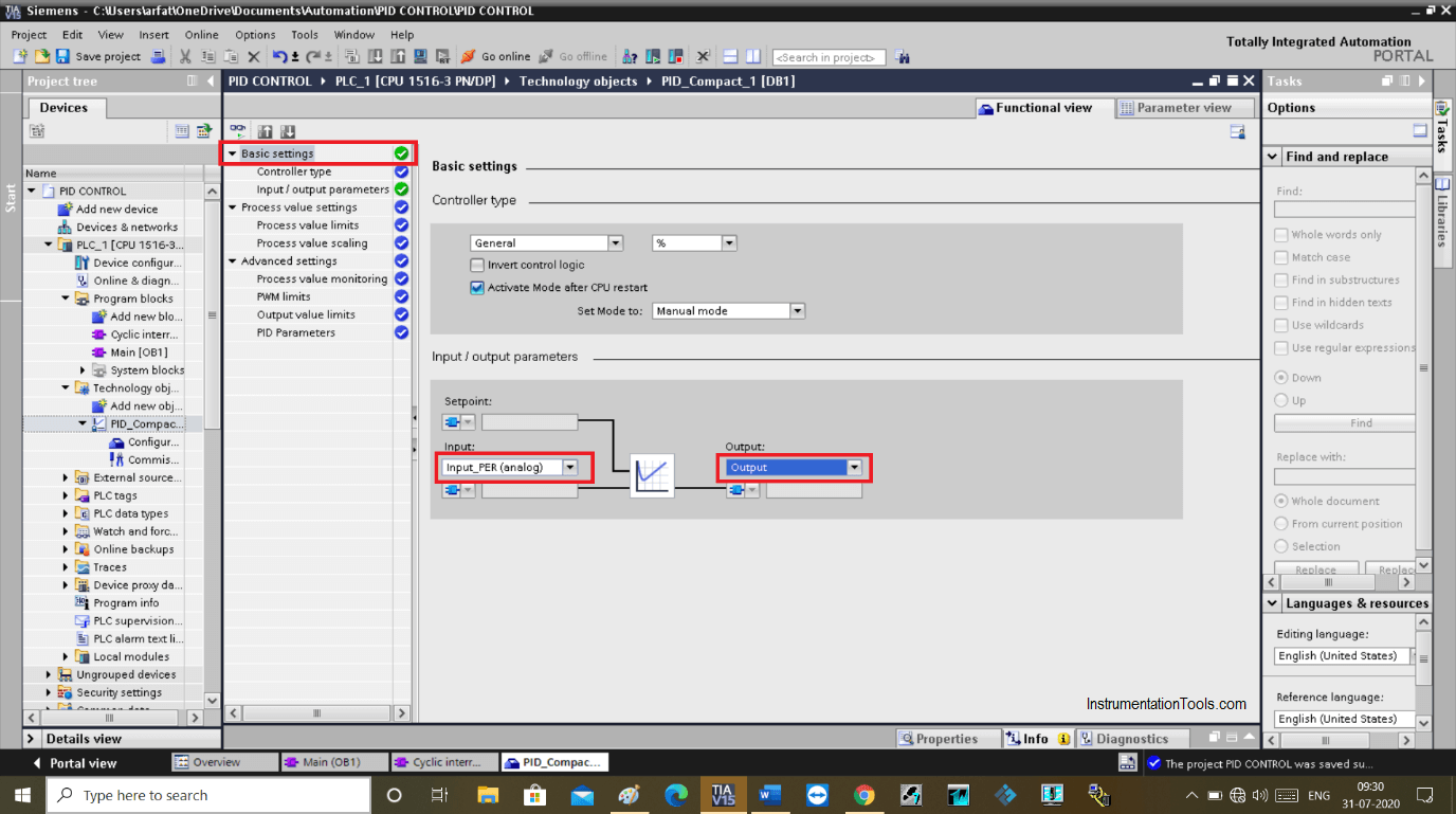
Here, In the PID block click on the configuration icon to configure parameter.

PID Compact

The following window will appear. Here, in “basic setting” in input/output parameter choose input “input (PER) analog”.

This is how in real processes value coming from the transmitter is converted to an engineering unit.

The same way choose an output in the “output” section.

Simple Examples of PID Control

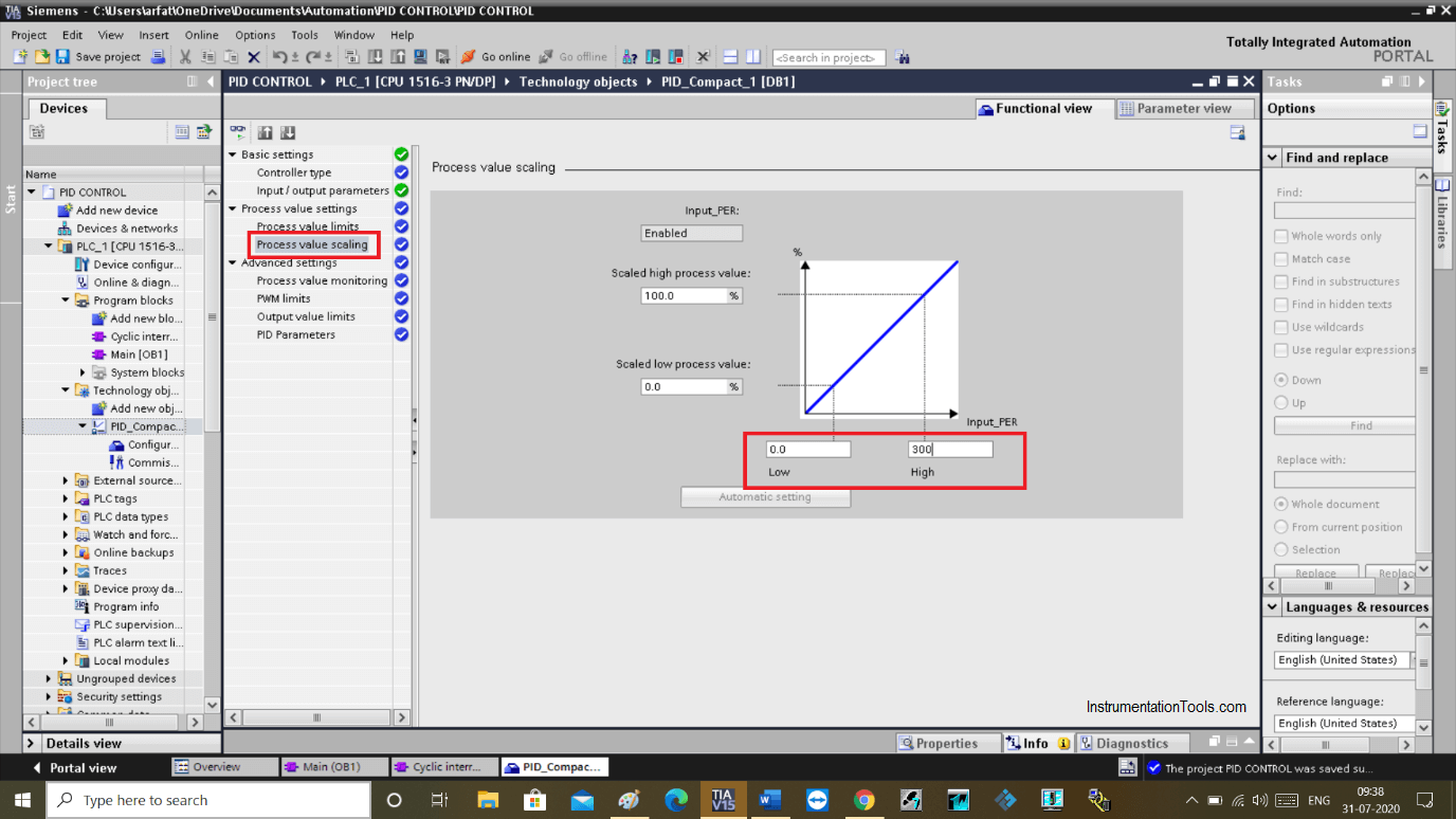
Now, in the “process value scaling” option in low and high value choose a value from 0 to 300 °C, as this a range of a temperature we selected earlier.

Example of PID

Now, let’s get back to the PID instruction. As we all know that the PID requires three main parameters a set point, a process variable, and a manipulated variable.

Here, I have defined tag to the main three-parameters.

Siemens PID

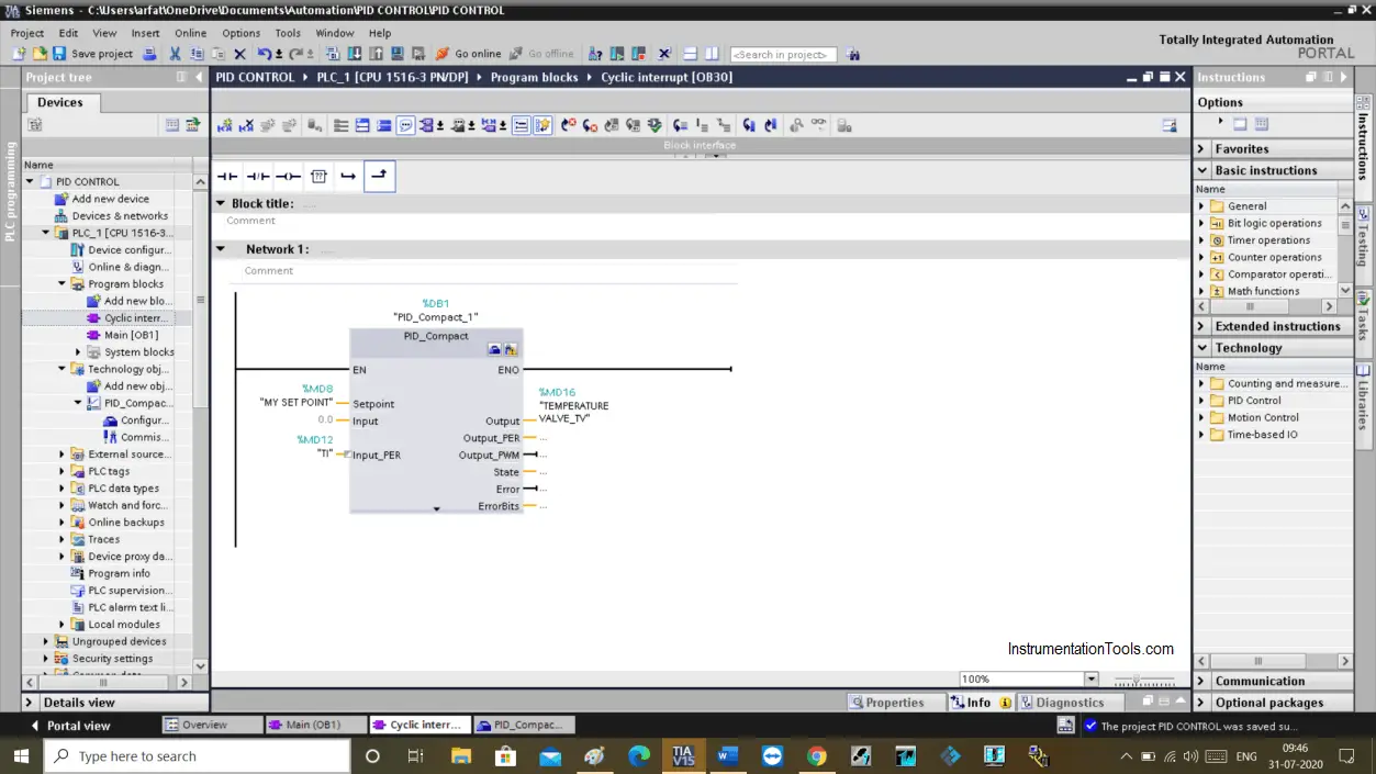
This is how actual programming is done to control a process.

You need a range of process variable, you need to know the temperature, level, pressure, flow (process variable) zero & span percentage. Create an equation and put it into the PLC programming.

I hope you may have a better idea about the PID block in Siemens PLC. If you have any doubts about it then feel free to put your question into the comment section.

Author: Suhel Patel

If you liked this article, then please subscribe to our YouTube Channel for PLC and SCADA video tutorials.

You can also follow us on Facebook and Twitter to receive daily updates.

Read Next:

  • PID Controller Functions
  • Control Valve Characteristics
  • Temperature Control System
  • DCS Program Draft Furnace
  • Instrumentation and Control
Don't Miss Our Updates
Be the first to get exclusive content straight to your email.
We promise not to spam you. You can unsubscribe at any time.
Invalid email address
You've successfully subscribed !
Up Counter PLC Program
PLC Ladder Program for Automatic Car Wash using Siemens TIA Portal
What is NOR Flash Memory in PLC?
What is Nest Loading? – DCS and PLC Control Systems
PLC Analog Input Conversion Formula
Share This Article
Facebook Whatsapp Whatsapp LinkedIn Copy Link
Share
Leave a Comment

Leave a Reply Cancel reply

Your email address will not be published. Required fields are marked *

Stay Connected

128.3kFollowersLike
69.1kFollowersFollow
208kSubscribersSubscribe
38kFollowersFollow

Categories

Recent Comments

  • Kamli on Top Free PLC Software
  • Guifty Shimica on Top Non-PLC Certification Courses for Automation Professionals
  • Guifty Shimica on Top Non-PLC Certification Courses for Automation Professionals
  • MIHARITSOA Aina Sitraka on Top Non-PLC Certification Courses for Automation Professionals

Related Articles

User Defined Data Types - UDT

User Defined Data Types (UDT) – Purpose, Need, Tutorial

Emergency Stop Push button

Emergency Stop Switch Spurious Trip

Siemens PLC

Five Types of PLC Programming languages

Electrical and Instrumentation Engineering Documents

Electrical and Instrumentation – Automation Pre-engineering Documents

running two single-phase induction motors sequentially

Control Two Motors in Sequence after Time Delay – Circuit, Operation

Wonderware Recipe Manager Plus

What is Recipe Management in SCADA?

Instrumentation and Control Project Packages

Instrumentation and Control Project Packages – Detail Engineering

Pulse Timer Instruction in PLC Programming

Pulse Timer Instruction in PLC Programming

More Articles

Solid State Devices Objective Questions and Answers

Top 300 Solid State Devices Objective Questions and Answers

What is Instrumentation and Control

What is Instrumentation and Control ?

Control Valve in Nutshell - Valve Design and Selection Factors

Control Valve in Nutshell – Valve Design and Selection Factors

Rotary Equipment

Modern Engineering Solutions for Rotary Equipment

Pressure Measurement

How to Measure Pressure in Inches of Water Column

Process flow diagram examples

What is Process Flow Diagram (PFD) ?

Absorber in absorption chiller

What is an Absorption Chiller? – Working Principle

The Role of CNC Machining in Electronics Manufacturing

The Role of CNC Machining in Electronics Manufacturing

Follow US
All rights reserved. Reproduction in whole or in part without written permission is prohibited.
Welcome Back!

Sign in to your account

Username or Email Address
Password

Lost your password?