A digital input, be it for PLC or any relay circuit, has two types of contacts – normally open (NO) and normally closed (NC). To design any electrical control circuit, a designer must be able to understand the difference between them and decide what to use for control.
One such circuit is for a stop button. It can be a normal push button used to stop a process or an emergency push button. Designers use NO or NC according to their convenience to design a circuit for stop buttons.
But, it is recommended to use the normally closed type for them. In this post, we will learn why to use normally closed circuits for stop buttons.
What is Normally-Open Contact?
As discussed earlier, NO stands for normally open. The NO contact is normally open, but when energized, it closes the circuit and allows the flow of electricity through it. When de-energized again, it opens itself and blocks the flow of electricity.
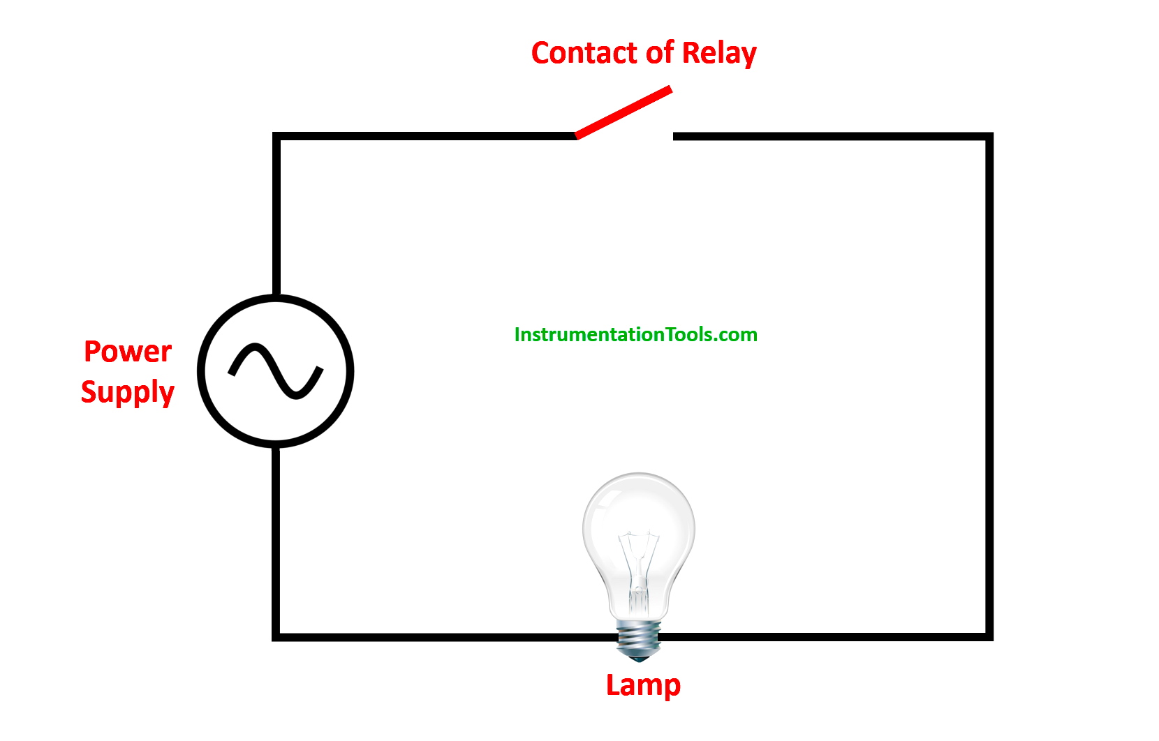
So, in open conditions, it is the normal state. Refer to the above image. When the relay is energized, its contact will close and allow current to flow from the power supply to the lamp. When the relay is again deactivated, its contact will open and stop the flow of current.
What is Normally-Closed contact?
As discussed earlier, NC stands for normally close. The NC contact is normally closed, but when energized, it opens the circuit and blocks the flow of electricity through it. When de-energized again, it closes itself and allows the flow of electricity.
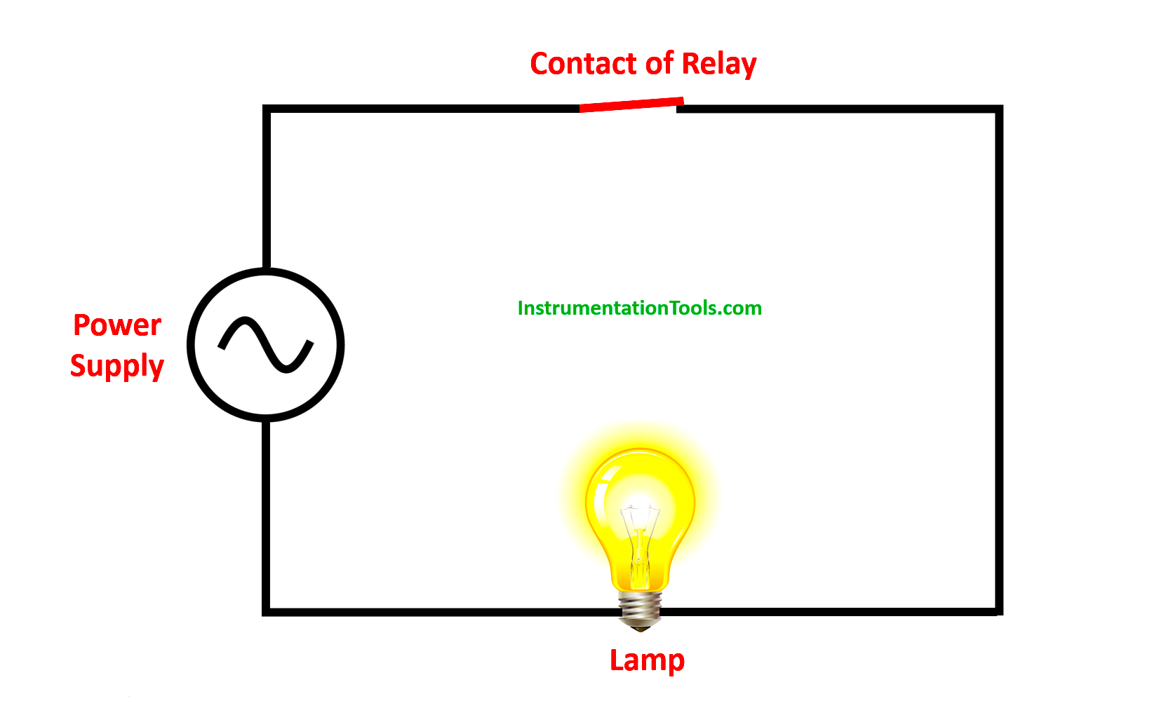
So, in the closed condition, it is the normal state. Refer to the above image. When the relay is energized, its contact will open and block current to flow from the power supply to the lamp. When the relay is again deactivated, its contact will close and allow the flow of current.
Why use normally closed contact for stop buttons?
Now, let us come back to our topic as we have understood the basics first. Consider we have taken three elements for understanding – a start push button, a stop push button, and a motor.
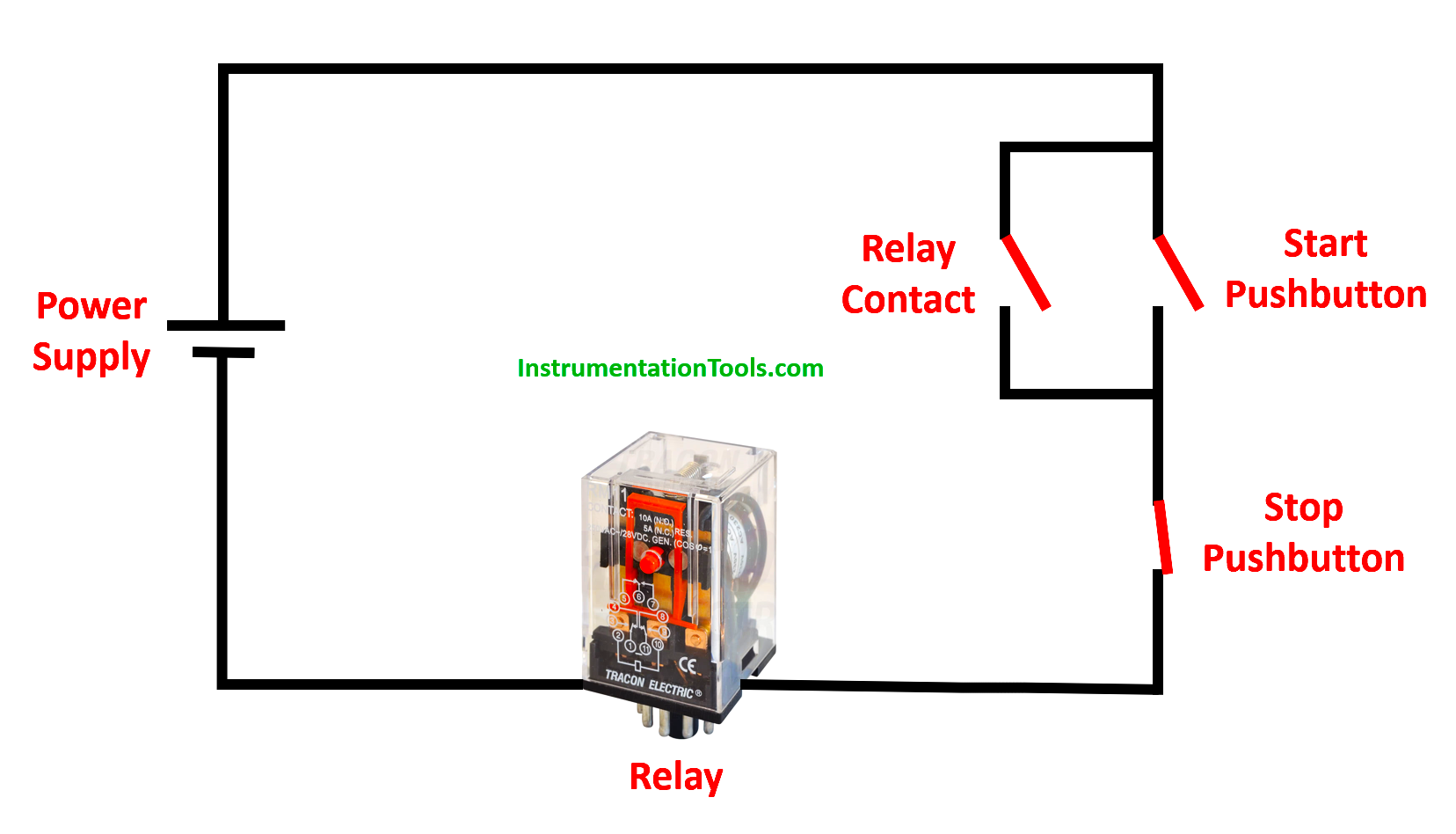
Refer to the below image for the circuit we have drawn. The motor is imaginary; it is triggered by a relay shown in the image. What we see here is the start pushbutton (PB) is normally open and the stop pushbutton (PB) is normally closed.
When the start PB is pressed, the power flows from the start pushbutton to the stop pushbutton and the relay triggers it. Once on, the relay contact will also get closed and latch the circuit. Now, even if the start PB is released, the power will flow from the relay contact latched.
Now, to stop the power flow, you have to press the stop pushbutton. If pressed, it will open and de-latch the relay. This will stop the power flow as both the start pushbutton and relay contacts are now open.
There are mechanical type stop buttons too in which it is normally open and it is always thus pushed up. This means it is behaving like a closed switch. When pressed, it will open the circuit and stop the power flow; which means the button has come back to its normal state.
The main advantage of using the stop pushbutton as NC is that suppose the wire breaks inside the contact. This means that it is open now. How many times do you press the start pushbutton; the power will not flow as the stop pushbutton is open now due to a wire break. This will alert the operator and ask him to troubleshoot the system. In short, the motor too will not get on and remain in a safe condition as the stop pushbutton is not working properly.
Now consider a scenario where the wire has broken in a normally-open stop pushbutton. The operator is pressing the button continuously, but it is not activating and not breaking the power flow. The motor is running abnormally and the system is not halting at all. This will damage the system.
Why this happened; because already the stop pushbutton was normally open and in that, its wire too broke; meaning open condition on open condition. So, it is thus not a good practice to use stop push buttons as normally open types.
This is because the normally closed contact as an input actuator won’t create dangerous situations under failure. Meaning that when a failure occurs (the wire-break), the input will act as the normally closed contact has been activated.
So, if the wire to the stop button breaks, the same will happen as if someone activated the stop button. The latch will break.
If you liked this article, then please subscribe to our YouTube Channel for Instrumentation, Electrical, PLC, and SCADA video tutorials.
You can also follow us on Facebook and Twitter to receive daily updates.
Read Next:
- Advanced PLC Online Course
- HRC Fuse Principle and types
- PLC Functional Block Diagrams
- Choose HMI for Your Application
- What is a Displacement Transducer?
- How to Test Battery with Multimeter?

