Sensors used to measure vibration come in three basic types: displacement, velocity, and acceleration.
Displacement sensors measure changes in distance between a machine’s rotating element and its stationary housing (frame). Displacement sensors come in the form of a probe that threads into a hole drilled and tapped in the machine’s frame, just above the surface of a rotating shaft.
Velocity and acceleration sensors, by contrast, measure the velocity or acceleration of whatever element the sensor is attached to, which is usually some external part of the machine frame.
Vibration sensors

A design of displacement sensor manufactured by the Bently-Nevada corporation uses electromagnetic eddy current technology to sense the distance between the probe tip and the rotating machine shaft.
The sensor itself is an encapsulated coil of wire, energized with high-frequency alternating current (AC).
The magnetic field produced by the coil induces eddy currents in the metal shaft of the machine, as though the metal piece were a short-circuited secondary coil of a transformer (with the probe’s coil as the transformer primary winding).
The closer the shaft moves toward the sensor tip, the tighter the magnetic coupling between the shaft and the sensor coil, and the stronger the eddy currents.
The high-frequency oscillator circuit providing the sensor coil’s excitation signal becomes loaded by the induced eddy currents.
Therefore, the oscillator’s load becomes a direct indication of how close the probe tip is to the metal shaft. This is not unlike the operation of a metal detector: measuring the proximity of a wire coil to any metal object by the degree of loading caused by eddy current induction.
In the Bently-Nevada design, the oscillator circuit providing sensor coil excitation is called a proximitor.
The proximitor module is powered by an external DC power source, and drives the sensor coil through a coaxial cable.
Proximity to the metal shaft is represented by a DC voltage output from the proximitor module, with 200 millivolts per mil (1 mil = 1 /1000 inch) of motion being the standard calibration.

Since the proximitor’s output voltage is a direct representation of distance between the probe’s tip and the shaft’s surface, a “quiet” signal (no vibration) will be a pure DC voltage.
The probe is adjusted by a technician such that this quiescent voltage will lie between the proximitor’s output voltage range limits.
Any vibration of the shaft will cause the proximitor’s output voltage to vary in precise step. A shaft vibration of 28.67 Hz, for instance, will cause the proximitor output signal to be a 28.67 Hz waveform superimposed on the DC “bias” voltage set by the initial probe/shaft gap.
An oscilloscope connected to this output signal will show a direct representation of shaft vibration, as measured in the axis of the probe.
In fact, any electronic test equipment capable of analyzing the voltage signal output by the proximitor may be used to analyze the machine’s vibration: oscilloscopes, spectrum analyzers, peak-indicating voltmeters, RMS-indicating voltmeters, etc.
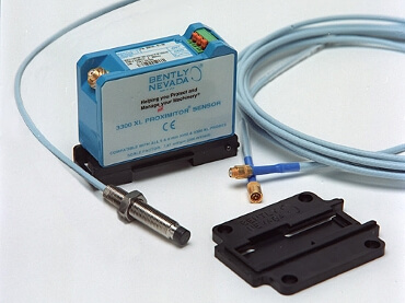
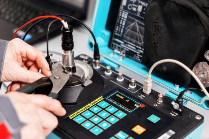
Photographs of a Bently-Nevada displacement sensor (sensing axial vibration on a “ring” style air compressor) and two proximitor modules are shown here:

It is customary to arrange a set of three displacement probes at the end of a machine shaft to measure vibration:
two radial probes and one axial (or thrust) probe. The purpose of this triaxial probe configuration is to measure shaft vibration (and/or shaft displacement) in all three dimensions:

It is also common to see one phase reference probe installed on the machine shaft, positioned in such a way that it detects the periodic passing of a keyway or other irregular feature on the shaft.
The “keyphasor” signal will consist of one large pulse per revolution:

The purpose of a keyphasor signal is two-fold: to provide a reference point in the machine’s rotation to correlate other vibration signals against, and to provide a simple means of measuring shaft speed.
The location in time of the pulse represents shaft position, while the frequency of that pulse signal represents shaft speed.
For instance, if one of the radial displacement sensors indicates a high vibration at the same frequency as the shaft rotation (i.e. the shaft is bowed in one direction, like a banana spinning on its long axis), the phase shift between the vibration’s sinusoidal peak and the phase reference pulse will indicate to maintenance machinists where the machine is out of balance.
This is not unlike automatic tire-balancing machines designed to measure imbalance in automobile tire and wheel assemblies: the machine must have some way of indicating to the human operator where a balancing weight should be placed, not just how far out of balance the tire is.
In the case of machine vibration monitoring equipment, the keyphasor signal and one of the axial displacement signals may be simultaneously plotted on a dual-trace oscilloscope for the purposes of determining the position of the imbalance on the machine shaft.
Credits : by Tony R. Kuphaldt


1st of all i would thank u 4 providing this article and its Needed more in detail so please make more detail if possible with animation
it is valuable and easy to understand working principle of vibration switches.
Very good & informative.
Could u please post some animations on above topics.
Keep continue posting new topics.
Thank you for useful blog!
Very useful and nice explanation on Vibration.
Thanks
Very informative and helpful artical
Very nice explanation…
Thank you guys a lot for this useful information about vibration sensors, I would wish you can keep on posting some more information.
Can oil on the shaft endluence the output